Completing Initial Configuration
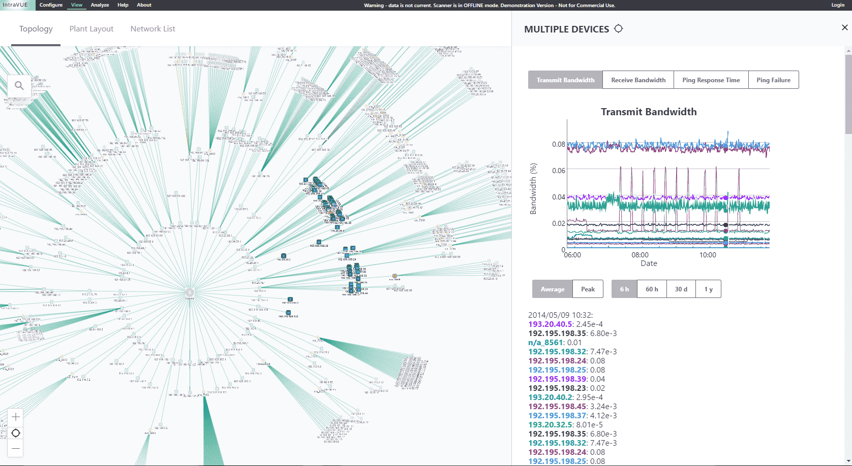
At the end of these steps your IntraVUE™ network(s) should look similar to this image.
- Open a browser and go to http://127.0.0.1:8765. Change 127.0.0.1 to the address of the remote IntraVUE host as necessary.
- Click on “Configuration”, sign in as an "admin".
![]() Change the default password for user 'admin' immediately to prevent unauthorized access to IntraVUE. Add additional users are necessary. Follow additional security measures as necessary.
Change the default password for user 'admin' immediately to prevent unauthorized access to IntraVUE. Add additional users are necessary. Follow additional security measures as necessary.
- Click on the “Scanner” tab.
- Change the default READ COMMUNITY name to the one used by the managed Layer 2 switches & routers. If you do not know it, leave it set to the default 'public'. Refer to Configure Menu - Scanner Tab
![]() Failure to enable SNMP read-only (RO) community on the managed routers & switches results in Unresolved NodesDevices under the Unresolved node will have all the functionality of other devices in IntraVUE. The Unresolved node serves as a placeholder for devices that can not be properly placed by IntraVUE with some information indicating the difficulty.. See IntraVUE Requirements in Installation & Registration before continuing.
Failure to enable SNMP read-only (RO) community on the managed routers & switches results in Unresolved NodesDevices under the Unresolved node will have all the functionality of other devices in IntraVUE. The Unresolved node serves as a placeholder for devices that can not be properly placed by IntraVUE with some information indicating the difficulty.. See IntraVUE Requirements in Installation & Registration before continuing.
-
Scan Speed: the speed of the IntraVUE™ scan engine (how fast IntraVUE packets are put on the network) can be conveniently adjusted with the Scan Speed control buttons. See Configure Menu - Scanner Tab
![]() Alert: Some very old Ethernet devices, e.g. PCL 5/40, may misbehave or reset when using Fast & Ultra scanner speed settings when not using the recommended setting, or when other scanning software is running in parallel on the same automation network. Check with Panduit IntraVUE Support to learn more before attempting to increase Scanner speed above the "Slow" value.
Alert: Some very old Ethernet devices, e.g. PCL 5/40, may misbehave or reset when using Fast & Ultra scanner speed settings when not using the recommended setting, or when other scanning software is running in parallel on the same automation network. Check with Panduit IntraVUE Support to learn more before attempting to increase Scanner speed above the "Slow" value.
- Add IntraVUE™ Networks under "Network Configuration".
Click 'Add' to create a new network
- Give it a meaningful name such as "PLCX" or "Conveyor Y"
- Give it the IP address of theTop ParentThe device that can provide the mac addresses for IP addresses in a network. :
 See Selecting The Top Parent for an explanation about the importance of the top parent IP address.
- Select what to scan:
- Scanning the Local Plant Network using the IntraVUE™ host:
- Check "USE LOCAL COMPUTER" and select one of the interfaces on the IntraVUE host itself.
- The scan range will auto populate based on the top parent's IP address. A class C IP address range is suggested but can be larger.
- Enter additional scan ranges that can be pinged from the IntraVUE™ host
- Click "Save & Scan Network" to save changes

- Scanning a routable network (or VLAN) using the IntraVUE™ host:
- Enter the gateway IP address of that routable network (i.e. typically the .1 address) as top parent
- The scan range will auto populate based on the top parent's IP address. A class C IP address range is suggested but can be larger.
 It is important to include in the scan range section the IP addresses of all of the fully managed switches in either or both the local, remote, and isolated networks. This is required for IntraVUE™ to do a cross matching of IP to MAC address and position the IP device on its actual physical location on the topology map.
 - Enter additional scan ranges that can be pinged from the IntraVUE™ host
- Click "Save & Scan Network" to save changes

- Scanning an un-routable network or isolated remote network using the IntraVUE™ Appliance as an Agent.
- Enter the designated IP address of the uplink port (typically LAN 1/IP1) of the IntraVUE™ Agent as the top parent
- Enter the IP address scan range of the isolated network(s) in both boxes of the scan range section
- Click "Save & Scan Network" to save changes

- Scanning the Local Plant Network using the IntraVUE™ host:
![]() When adding multiple networks, make sure fill out all fields for each subsequent network in order to get prompted to "Save & Scan Network".
When adding multiple networks, make sure fill out all fields for each subsequent network in order to get prompted to "Save & Scan Network".
- IntraVUE will now begin scanning. Click on "View" on the top navigation menu to return to the Topology view and see scanning discovery process.
- Allow a few minutes (depending on the number of nodes) for IntraVUE to start building your network topology.
When new devices are added the IntraVUE Scanner will spend several minutes developing the Network Topology. Viewing at this time will not provide an accurate depiction of the topology.
Initially IntraVUE will show all discovered devices linked to a special Unresolved node connected to the top parent.
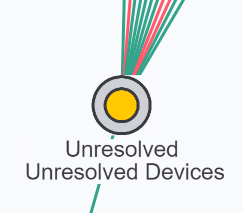
As soon as a device responds to a ping it is placed under the Unresolved Devices node and the individual nodes. During this period IntraVUE first attempts to find MAC address information from the top parent and any local routers or layer 3 switch.
![]() One cause of IntraVUE not determining the MAC address is an incorrect or missing SNMP read-only community setting in a managed router's own configuration, or in the IntraVUE System Configuration Scanner's tab, "Default SNMP Read Only community". This is usually set to 'public'.
One cause of IntraVUE not determining the MAC address is an incorrect or missing SNMP read-only community setting in a managed router's own configuration, or in the IntraVUE System Configuration Scanner's tab, "Default SNMP Read Only community". This is usually set to 'public'.
Once the MAC address has been determined, IntraVUE attempts to find the correct location in the network hierarchy to place the device.
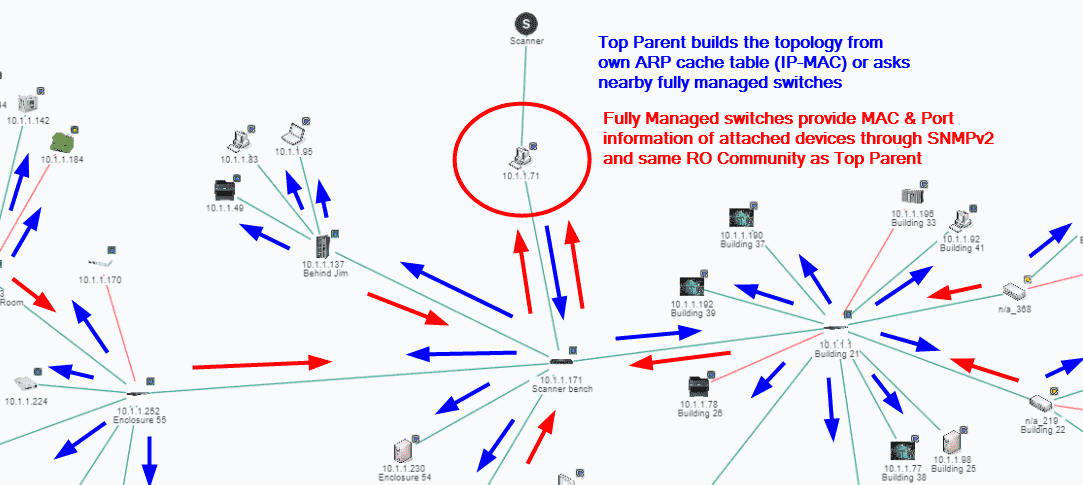
If the IP of the device is in the same subnet as the top parent it will be moved to the top parent pending a move to a managed switch. If it is in a different subnet from the top parent of that Intravue network, it will remain in unresolved unless a router having an interface for that IP is discovered or a managed switch claims its mac address on a port. In those cases the device will move out of unresolved. This situation could occur due to an incorrect community in a router or switch, or its switch is not in the scan range.
Devices under the Unresolved node will have all the functionality of other devices in IntraVUE. The Unresolved node serves as a placeholder for devices that can not be properly placed by IntraVUE with some information indicating the difficulty. See also Selecting The Top Parent.
In the case that switches in a different subnet can not provide MAC information because of lack of access to SNMP on router that bridges the other subnet, you can enable the option "Use SNMP provided MAC" which will provide the MAC address from the SNMP of the switch. See also Device Configure - SNMP.
An unmanaged switch that has an IP address but which does not support SNMP will be found and displayed under an auto-inserted node along with the devices that are directly connected to the switch. This is because they will all be found on the same port of the unmanaged switch’s parent and any lower down managed switches will see them on the 'uplink' port back toward the IntraVUE™ host.
The image below shows the way IntraVUE™ will display an unmanaged switch that has an IP address having two devices connected to it. If a managed switch does not have its SNMP community set correctly it will appear the same. The 10.1.1.163 device is an unmanaged switch with the .161 and .20 devices physically attached.
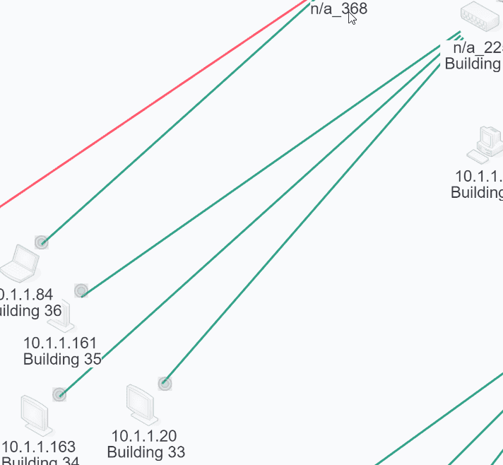
The parent managed switch of these devices reports them all on the same port, so IntraVUE™ automatically inserts a node, labeled 'n/a' to represent the hub or unmanaged switch which must be present.
To learn the difference between 'n/a' nodes and 'N/A' nodes see NA Nodes for more details.
In order to show the network as it physically exists the administrator can select the Configure item from the unmanaged switches Device Menu. Check the checkbox 'Unmanaged Switch or Wireless AP' or 'Virtual Machine, Web Managed Switch, Access Point' on newer IntraVUE versions. Click 'Save Changes'.
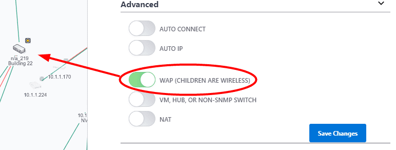
After a minute, the auto inserted node will go away as there is now only one device on the port of the managed switch and the other two devices are below it.
![]() Some old unmanaged switches and hubs don't have a IP address by default or because of missing configuration. IntraVUE will not be able to see these without an IP address. In order to show the network as it physically exists you can add child nodes and move attached devices under this unmanaged switch. This is not recommended as monitoring for that switch is very limited.
Some old unmanaged switches and hubs don't have a IP address by default or because of missing configuration. IntraVUE will not be able to see these without an IP address. In order to show the network as it physically exists you can add child nodes and move attached devices under this unmanaged switch. This is not recommended as monitoring for that switch is very limited.
Similar to unmanaged switches, a virtual hosts server will display an 'n/a' node with devices physically attached it. In order to show the network as it physically exists the administrator can select the 'Configure' item from the virtual machine's Device Menu. Check 'Virtual Machine, Web Managed Switch, Access Point' and then Click 'Save Changes'. After a minute, the auto inserted node will go away as there is now only one device as the virtual host and the other devices are below it.
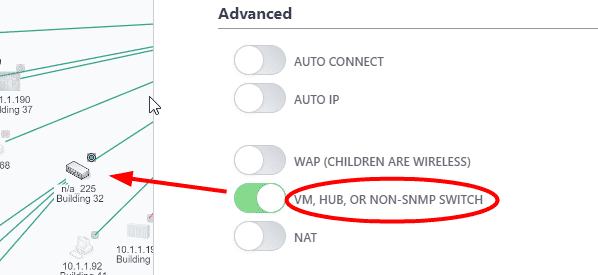
Managed Wireless APs should be discovered by IntraVUE™ and will automatically get the checkbox for 'Virtual Machine, Web Managed Switch, Access Point' in the Device Configure dialog checked. If you have a Wireless AP that is not managed, you can check the checkbox yourself.
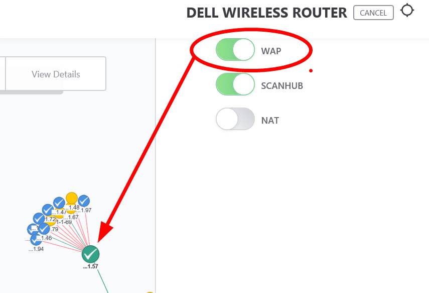
The result will be that all wireless devices will appear under the Wireless AP.
To identify the Wireless AP network better in the IntraVUE UI, you can check the 'WAP' checkbox and the child nodes will have dashed, wireless, lines going to them.
Refer to for more details
IntraVUE can map certain ring topologies as long as they are based on PROFINET or Ethernet/IP technology. DLR network topologies is the most common in which having each drive connecting from the first one to the last one back to the same EtherNet/IP nic card's port. The drives are fixed so they won't move around. See Device Level Ring (DLR) Networks for more details. Switch rings are not being detected currently by IntraVUE 3.1.
![]() IntraVUE will only detect nodes that can be verified through a simple ping command in DOS.
IntraVUE will only detect nodes that can be verified through a simple ping command in DOS.
- Not seeing devices: disable active windows firewall rules on the IntraVUE host machine or ACLs on the network. See System Requirements in Installation & Registration
- Missing devices or Topology no branching out correctly: See the Selecting The Top Parent, & Configure Menu - Scanner Tab
Disconnected Top Parent Nodes
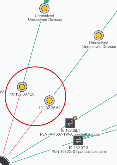
Some Top Parents may appear as disconnected after being visualized.
These nodes would appear with a red connection while the rest of topology has a green connections. This does not affect scanning the rest of the topology but simply means that IntraVUE™ discovered a disconnected device.
If the disconnected device is a top parent node (e.g. a router or L3 Switch) simply reconnect that device back online, or select a top parent that it's live and can be reached by the IntraVUE™ server.
Stopping IntraVUE because of presumed strange behavior in the Network
The IntraVUE Scanner works similarly to a SCADA scanner where it will ping the end devices without trying to write any information or causing them to malfunction.
IntraVUE will only report the health status of your network and never will try disrupt your network in any way, unless you have purposely set your scanner speed to 'Ultra' and you have very old automation devices.
 It is always best to start scanning with the "Slow" scanner speed even if it takes longer to find devices. IntraVUE™ is known for scanning automation networks, but many times increasing the speed or having bad switches can react strangely and cause device issues around the same time IntraVUE™ is running. See "Known issues" under FAQs
The KPIsKPIs are assorted variables that organizations use to assess, analyze and track manufacturing processes. These performance measurements are commonly used to evaluate success in relation to OEE goals and objectives System on the next section requires that you set critical status for each device you want to get metrics for UptimeThe portion of the OEE Metric that represents the percentage of scheduled time that a device is available to operate. Often referred to as Uptime and IncidentsIncidents includes all events that cause stop time on planned production for an appreciable length of time (typically minutes or hours). That is, incidents cause availability Loss from unplanned events (e.g. equipment failures). It is calculated like this: Availability = Run Time / Planned Production Time Run Time = Planned Production Time − Stop Time. Critical Status is not required to finalize the initial configuration but we still encourage you to visit the next section "IntraVUE Analytics" for coverage on this topic. The Device List View shows the current state of KPI Critical Status for each node.
The Device List view is a report view that lets you see network information related to all devices visible in either the Topology or Plant Layout views.
- IP Address: The IP of the Device
- Network Name: The IntraVUE network the device is configured with (See Configure Menu - Scanner Tab
- Device Name: From CIP or Netbios. Can be modified here (See below).
- Critical Status: See Device Configure - General & IntraVUE Analytics. Can be modified here (See below).
- Admin Verified: See Admin Verification in IntraVUE 3. Can be modified here (See below).
- Type: Device or Switch. Can be modified here (See below).
- Revision: e.g. ENETIP Rev 7.01. Can be modified here (See below).
- Vendor: e.g. Rockwell. Can be modified here (See below).
- Model. e.g. 1756-EN2TR. Can be modified here (See below).
- Location: e.g. Electrical Room
- User Defined 1. Custom field. See Device Configure - Other Names

 Selecting the IP address of a device will center that device in the Topology View.
Modify a Field directly from Device List View:
- Open a browser and go to http://127.0.0.1:8765. Change 127.0.0.1 to the address of the remote IntraVUE host as necessary.
- Log in from the right-top corner using the default password "intravue".
- By clicking on "Device List", you will see a list of all devices found.
- Change the either Device Name or Critical Status by clicking double clicking on the actual value for that device until you notice that the value becomes editable. Most values are editable
- When done click on an empty area away from the field until you get a blue "Save Changes" button. Click on it to save changes and move to the next row. Continue doing this for devices that need changes.
- Open a browser and go to http://127.0.0.1:8765. Change 127.0.0.1 to the address of the remote IntraVUE host as necessary.
- Click Configure to access the system menu and click on the “Email” tab.
- Check the 'Enable Email' checkbox to activate email alarms.
![]() Note that on a new scan checking this checkbox will not result in ANY emails being sent. That is because, by default, no device will have its 'Send Email to Default User' checked (See Settings Required on Device Configuration Below).
Note that on a new scan checking this checkbox will not result in ANY emails being sent. That is because, by default, no device will have its 'Send Email to Default User' checked (See Settings Required on Device Configuration Below).
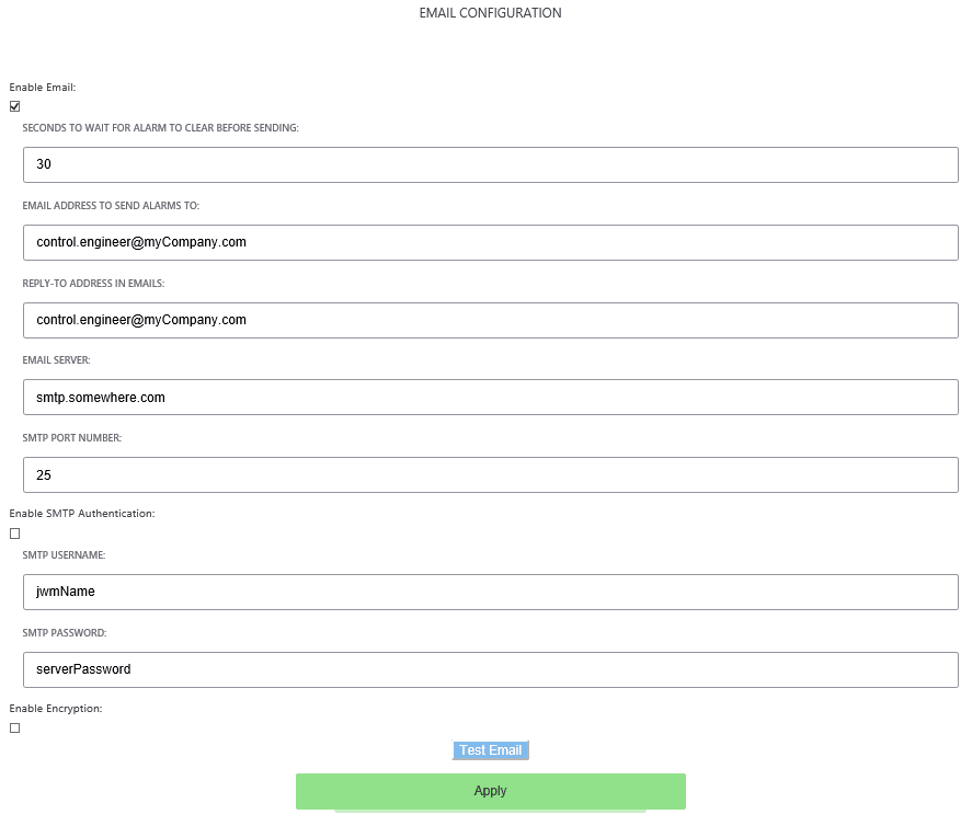
- The "SECONDS TO WAIT FOR ALARM TO CLEAR BEFORE SENDING" box sets the number of seconds an email alarm will be delayed before transmission. At the end of the delay time, IntraVUE will check to see if the alarm condition is still valid. If it is, the email will be sent at that time. 30 seconds is the default setting.
- The "EMAIL ADDRESS TO SEND ALARMS TO" box field is the email address that will receive the email alarms for all devices. If there are more than one recipient you want to send emails alarms to separate each email address with a comma (e.g. user1@company.com, user2@company.com, etc).
- The "REPLY-TO ADDRESS IN EMAILS" box is required when your SMTP server requires a valid email address when emails are bounced back. It is also the reply to address that will be on the alarm emails (i.e. the "From" field). This email address may or may not have to be valid depending on your SMTP server.
- The "EMAIL SERVER" requires the mail STMP server that will relay emails from IntraVUE™ to the email(s) on step 5 above.
- The "SMTP PORT NUMBER" is necessary to connect to the SMTP server that will be relaying the email. Port 25 is the common.
 It's best to use a company SMTP server as public SMTP servers (e.g. gmail or yahoo mail) could take a long time to receive alerts.
- SMTP Authentication and Encryption are optional and not required by IntraVUE to sent alerts.
- The "Test Email" button will will immediately generate a test email using the settings entered in the earlier steps. If you make a change, select the APPLY button before selecting "Test Email". This feature avoids having to disconnect a device just to test your email settings.
Settings Required on Device Configuration
In the Device Configure - General, click 'Edit', 'Send Alarms' button. This is NOT enabled by default. If enabled the default user (specified under Configure > Email) will get email alerts for this device.
There is also an 'Send Alarms to Default User' button. If you want an additional email sent to someone besides the default user, click this button AND edit the 'Alarm Email Address' field for the email of the person to get email alerts for this particular device.

When the "Test Email" button does not work
When you use the Test Email button and you do not receive an answer, there will be some text in an Exception message indicating the specific cause of the failure. For instance refused by SMTP host, invalid user name or password, etc.
This message is found in the scanner log file located at ...\intravue\log and will be the ivserver_(date)_(time).out file at the time you pressed Test Email.
| A sample of what is generated. It was generated by doing a Test Email with the default Email Setup dialog. The stacktrace line "javax.mail.MessagingException: Unknown SMTP host: smtp.somewhere.com;" tells you that the SMTP host, the email service provider, is incorrect or that you can not connect to it. | 0120 100016 event: Device 10.1.1.67 reconnected 0120 100054 event: Device 10.1.1.90 moved from 10.1.1.244:9 to 10.1.1.16:2 0120 100054 event: deleted child node at 10.1.1.244:9 0120 100111 event: 10.1.1.32 Ping Response Threshold Exceeded 0120 100122 received mod request send test email 0 0 0120 100122 send test email 0120 100123 EmailTask runs: Intravue has been instructed by the admin to send a test email. Please see http://10.1.1.59:8765/ to [unused] 0120 100123 Unexpected Exception thrown - stacktrace follows: javax.mail.MessagingException: Unknown SMTP host: smtp.somewhere.com; nested exception is: java.net.UnknownHostException: smtp.somewhere.com at com.sun.mail.smtp.SMTPTransport.openServer(SMTPTransport.java:1211) at com.sun.mail.smtp.SMTPTransport.protocolConnect(SMTPTransport.java:311) at javax.mail.Service.connect(Service.java:233) at javax.mail.Service.connect(Service.java:134) at javax.mail.Service.connect(Service.java:86) at com.sun.mail.smtp.SMTPTransport.connect(SMTPTransport.java:144) at javax.mail.Transport.send0(Transport.java:150) at javax.mail.Transport.send(Transport.java:80) at database.EmailTask.run(EmailTask.java:76) at java.util.TimerThread.mainLoop(Unknown Source) at java.util.TimerThread.run(Unknown Source) 0120 100146 device 10.1.1.67 disconnected 0120 100146 event: Device 10.1.1.67 disconnected 0120 100207 device 10.1.1.90 reconnected |
IntraVUE™ will generate an email alarms for the following events:
- Device x.x.x.x disconnected - See Event Log Descriptions
Subject: "Intravue alarm ip=w.x.y.z"
- Body: "Intravue reports device w.x.y.z has disconnected. Please see IntraVUE™ Link"
-
Device x.x.x.x reconnected - See Event Log Descriptions
-
Subject: "Intravue alarm ip=w.x.y.z"
- Body: "Intravue reports device w.x.y.z has reconnected. Please see IntraVUE™ Link"
-
Customizing the Email Message
The email message that is sent to the user can be customized. See The ivserver.properties File.
- The email subject line can be customized to include the device name.
- The email body for a device disconnected message can add the device name and link.
- The ip address used to provide a link to the IntraVUE host can be changed to allow users requiring a proxy address rather than the real host address to reach the IntraVUE browser.
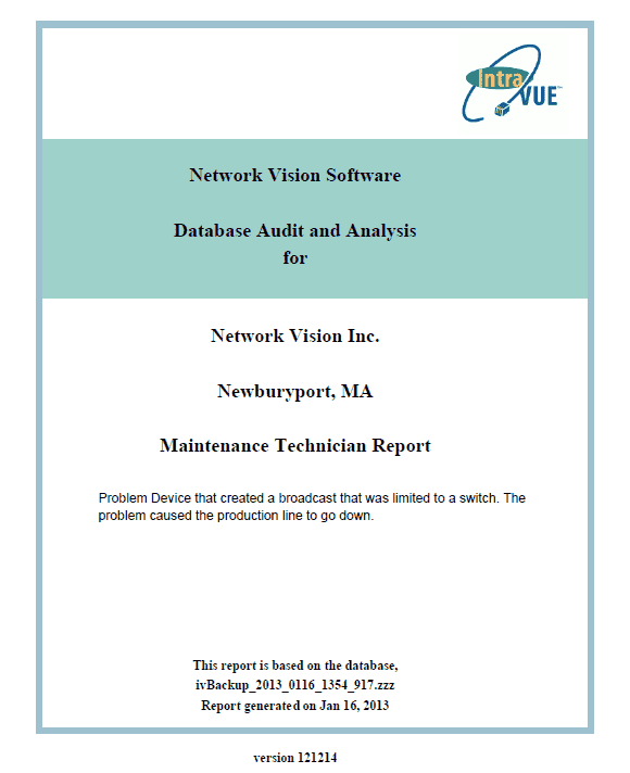
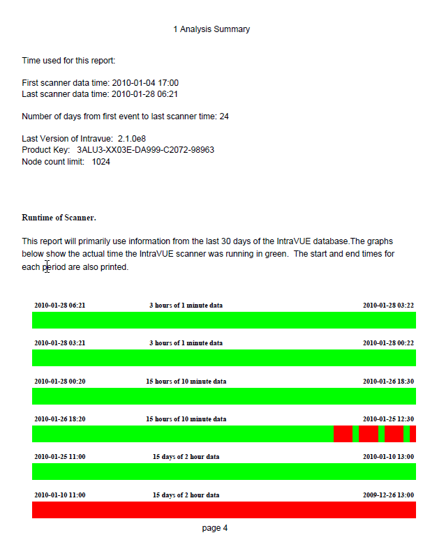
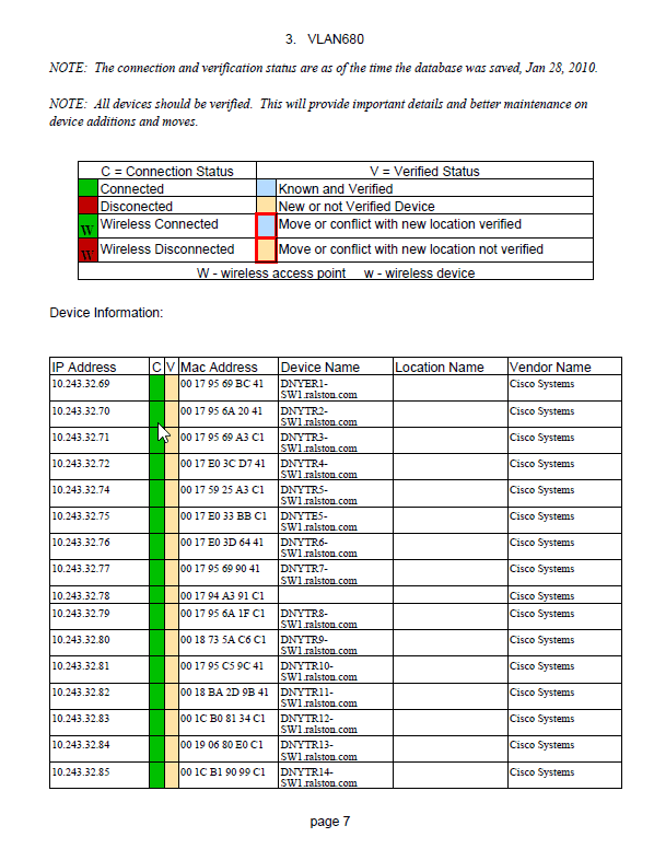
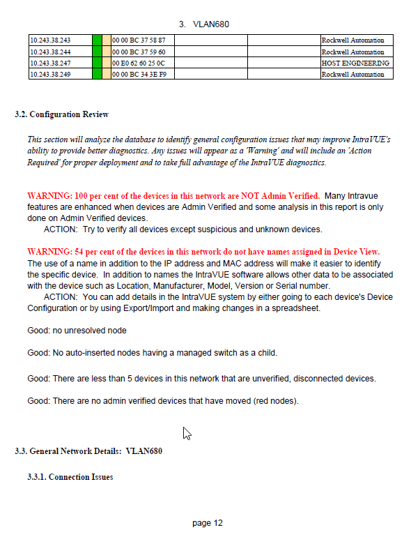
The IntraVUE On-Demand System Analytics are an additional capability of IntraVUE that will automatically generate written reports that identify issues as well as suggested courses of action for many common problems that can occur on Industrial Ethernet Networks. They can be generated in minutes and contain the latest data contained in the IntraVUE system.
The IntraVUE On-Demand System Analytics provides you with a PDF report based on the analysis of your IntraVUE System available anytime 27/7/365*.
Once an account is established you will be able to upload a Support Archive and get the resulting network analysis & diagnosis report. The process takes about a minute to upload, two - three minutes for analysis, and then the report will be emailed to you**.
|
|
|
|
- Create a support archive (i.e. *.zzz file). See Generate Support Archive
- Either use the "Send Archive" button (See Generate Support Archive) or click on the link below to be redirected to the Analytics Reports portal http://intravue.panduit.com:8765/IntravueAudit/AuditServlet
- Login to the IntraVUE Report Generator by entering your primary email address and password.
 If this is your first time, enter your email address and desired password and click "New User" to register.
- Enter Company Name, Location, Comments, Report Type (Maintenance for troubleshooting and Configuration Analysis for IP scan ranges),
- Select which colums to show (e.g. MAC address, Vendor, Model). Click "Apply Data"
- Select "Choose File" and browse to your *.zzz file location & click 'Upload Archive For Analysis'. Wait "Success: archive uploaded" message.
- Click "Analyze database and email results".
- A message "The archive is being processed and the results will be emailed to you in minutes with the PDF report attached" would appear when done. You can start a new report* or close your browser.
- If you are not receiving diagnostics reports or can not login to the Analytics Reports portal contact techsupport@panduit.com.
*There's no limit on the number of Analytics Reports you can request.
**IntraVUE Advanced Subscribers automatically get a remote assessment of the IntraVUE Plant Network from one of our IntraVUE experts who will review their On-Demand System Analytics & Diagnosis Report and discuss with you recommendations, suggestions, and potential solutions to prevent, improve, or resolve network issues.
![]() Skip this step if you are using a only setting up a Software Package (SNMS / SNMA). This section only applies to customers that have purchased the IntraVUE Appliance.
Skip this step if you are using a only setting up a Software Package (SNMS / SNMA). This section only applies to customers that have purchased the IntraVUE Appliance.
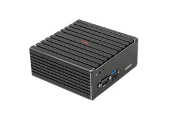
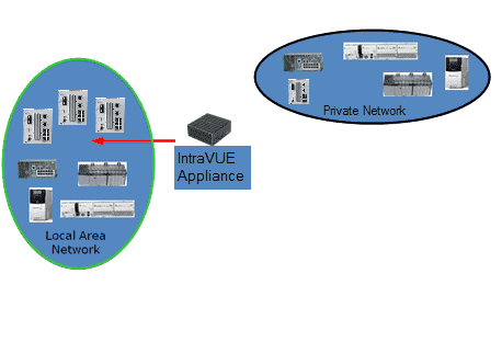
The IntraVUE Appliance is a small-factor headless appliance strategically placed in a network closet at a remote site with the purpose of scanning edge devices in one or multiple cases below:
1. Devices in an isolated network behind a gateway. A switch inside the 'isolated network' behind a gateway using one port of the agent and the other port of the agent is connected to a switch on the 'plant' side (or plant VLAN Access) network.
2. Private VLANs. One is the private VLAN of the 'system' and the other provides access from the 'plant' to the PLC of the 'system'. The IntraVUE Agent has one interface connected to a 'system VLAN' port of the switch and the other agent's Ethernet interface is connected to a 'plant VLAN' port of the same switch.
3. If a NAT, or Firewall Access to the NAT, or Firewall devices is configured to send all packets from an IP address on the plant side to the IP of the IntraVUE agent on the 'system' side of the NAT/Firewall, then the IntraVUE Agent can scan the devices behind the NAT, or Firewall.
Using IntraVUE Appliance as an Stand-alone Server to scan the Plant Network:
When there is no physical server or virtual machine available, the small-factor headless appliance can be deployed as an IntraVUE Server. The only differences is that it does require software registration and only one port of the appliance is connected to a switch on the 'plant' side.
![]() See Using the IntraVUE Appliance as an Agent for more details
See Using the IntraVUE Appliance as an Agent for more details
![]() See also Using the IntraVUE Appliance as a Server for more details
See also Using the IntraVUE Appliance as a Server for more details
![]() See IntraVUE Appliance Configuration for exact deployment and configuration steps
See IntraVUE Appliance Configuration for exact deployment and configuration steps
Admin Verification is a process of establishing a controlled state of your network, or the devices which you are monitoring with IntraVUE.
 Rogue devices can be easily identified when all devices have been previously verified (see below) and when using device filters (see View Filters)
 Refer to IntraVUE Legend to understand node fill, outlines, and connecting line colors.
Each Admin Verified node has additional characteristics from a non-Verified node.
 The node is normally blue filled.
 If the position of the device changes the originally verified position becomes red filled.
 The new position of the device becomes a tan filled node.
 If the device that moved comes back to the original location, the tan filled node will go away and the red filled node will become blue filled again.
![]() Failure to admin verify all of detected devices by IntraVUE will result in incomplete Analytics & KPIs Status Reports, missing configuration of newly detected devices, inability to detect when a device has moved or disconnected from ring or linear networks, and impairs your ability to identify what assets truly belong to your plant network and troubleshoot them accordingly.
Failure to admin verify all of detected devices by IntraVUE will result in incomplete Analytics & KPIs Status Reports, missing configuration of newly detected devices, inability to detect when a device has moved or disconnected from ring or linear networks, and impairs your ability to identify what assets truly belong to your plant network and troubleshoot them accordingly.
When a node is tan filled it will stand out. It will call your attention to it. Find out what it is and then verify it or take some action to get the device off line.
A second tan filled node is the 'ghost' of the real position of a device. The real device will have a real IP name like 1.100.56 and the ghost node will have the IP 10-1-100-56.
If you see a tan filled node, find the corresponding tan filled node with dashes in the IP address.
If the new position is acceptable, delete the ghost tan filled node and admin verify the new position. In the future this two step process will become one step.
If the position is temporary, you may leave the red filled ghost. When the device is returned to its former position the red ghost will be replaced by a blue filled node.
To make Admin Verification easy, there is a single button that will automatically verify every device with an IP address that has not yet been verified. It's on the Scanner Tab of the Configure Menu - Scanner Tab. See also Device Configure - General for verifying individual nodes.
![]() Recommended: Take a snapshots of your database and user settings. Refer to
Recommended: Take a snapshots of your database and user settings. Refer to
