Installation & Registration
What do I need to know before installing IntraVUE™?
Follow these 9 steps to install IntraVUE and quickly Discover, Map, Monitor and Diagnose the health of your industrial plant network.
Step 1:
Request a demo or official license to run either the POC, Assessment, or IntraVUE installation from techsupport@panduit.com.
Step 2:
Designate which Windows workstation, server, virtual, appliance, Raspberry Pi, etc., will be utilized. Refer to the System Requirements.
Step 3:
Define the preferred scanning location. The ideal place is where IntraVUE can successfully ping all edge devices (e.g. the core switch). Refer to IntraVUE Placement.
Step 4:
Assure SNMP is enabled in all fully managed switches. Know the read only community that can be configured in IntraVUE if it is not the default of 'public'. See System Requirements on what is considered a fully managed switch.
This is not mandatory. You can still monitor edge devices and view the network topology with some manual work.
Step 5:
Identify the IP scan ranges of all devices.
Step 6:
Install and register the latest version of IntraVUE. Refer to IntraVUE Installation & Registration.
Step 7:
If Access Control Lists (ACLs) or management lists are configured in managed switches, make sure the IP of the IntraVUE host is configured to allow access. Refer to the IntraVUE System Requirements to open access for the communication ports.
Step 8:
Select the first network and start scanning. Make sure there are no devices that stay in 'Unresolved' and that devices move under the managed switches. If switches are in a different network, they must be included in the scan range of the network chosen. Once the first can is complete, continue by adding the remaining networks. Refer to Completing Initial Configuration.
Step 9:
Create your Plant Documentation. Refer to Creating Plant Documentation
This check list can also be downloaded here
The IntraVUE™ system and configuration requirements are shown below. Because IntraVUE is used in industrial automation environments, the next requirements are meant to make running IntraVUE easy.
Host System Requirements
| Server | |
| Processor | Dual Core with Cache (minimum), Quad Core with Cache (preferred), however, IntraVUE has been designed to work with any modern low power processor. Hyper-Threading recommended only when IntraVUE is installed on a virtual machine. |
| RAM (available) | 2 GB: Up to 500 nodes, 4 GB: 500+ nodes, 6 GB: 1000+ nodes, 8 GB: 1500+ nodes |
| Free Disk space | 4 GB: Up to 500 nodes, 6 GB: 500+ nodes, 8 GB: 1000+ nodes, 12 GB 1500+ nodes |
| OS |
Workstations OS: Windows 7 32-bit and 64-bit, and Windows 10. Server OS: Windows Server 2008, 2012, and Server 2016. Vista, and Windows 8 (and variants) are not certified nor recommended. Linux: Only available on a pre-configured VMWare Virtual Machine image. Click here for more information. When installing on Windows 7 ALWAYS choose a folder outside Program Files to avoid read-only file permission problems. We recommend a folder such as C:\IntraVUE. If you install on a Server based system, you MUST use the Add Programs function of Control Panel's Add/Remove Programs. |
| Virtualization | Any hypervisor platform that supports the operating systems above and that has a fixed virtual machine ID (VMID) not susceptible to high-availability changes is required. |
| Required Software |
(Java JRE will be automatically installed as part of the IntraVUE™ installation). User interfaces does not make use of java. Only used for the scanning engine. Java 6 should be uninstalled to avoid unexpected behavior of IntraVUE™. The latest Java JRE 32-bit at the time of the build will be installed as part of IntraVUE™ Installation. In 64-bit windows computers, only the 32-bit version of the Java Runtime Environment (JRE) should be installed (i.e. under C:\Program Files(x86)\Java). |
| Antivirus / Anti-Malware | Antivirus software must be disabled/turned off during the installation. You can turn them back on when the installation completes. You may have to configure your AV exclusions to skip the C:\intravue folder in order to allow the IntraVUE™ installer to complete installation. |
| Database |
(Maria DB will be automatically installed as part of IntraVUE™ Server Installation and removed as part of the IntraVUE™ uninstaller). *The C:\MySQL folder must be excluded from being backed up or analyzed by virus checking programs. The programs will lock critical, large files and cause the mysql service to stop if it cannot access certain files for longer than a few seconds. Should this occur, restarting the msyql service always works, but there will be no IntraVUE data collected while mysql is stopped. |
| Web Server | (eTomcat will be installed as part of IntraVUE™ Server Installation). This is used by the user interface. |
| Client | |
| Web Client | Any browser that supports HTML 5 and JavaScript is required. Recommended browsers include Chrome (most recent), Firefox (most recent), and Internet Explorer 11(or most recent). |
| Mobile | |
| Mobile Client | Android smart phones and tablets 5.0 (or newer versions recommended). iPhone devices will be supported in the future. |
IntraVUE Scanning Requirements
| SNMP Requirements in detail | |
| Fully Managed Switches: |
These switches must conform to the minimum SNMP standard RFC 1493 (or one of its successors) and respond to the Bridge MIB, or the Q-BRIDGE-MIB (RFC 2674 or one of its successors) in the case of newer Fiber Switches. See Verifying SNMP on Fully Managed Switches before attempting to buy switches that advertise as such but do not confirm with these SNMP standards. |
| SNMP Support: | SNMP must be enabled on all Fully Managed Switches |
| SNMP Community | Fully managed switches must have at least one Read-Only community (e.g. public) available |
| Local access to devices: | The host server must be able to PING all the devices in the scan range |
| Layer 3 Routing: | Gateway address required when monitoring remote subnets or VLANs |
| Access Control Lists: | May need configuration to allow scanning using required ports (See below) |
| Firewalls / Intrusion Systems: | May need configuration to allow scanning using required ports and protocols |
| HTTP Access | Required to allow remote access to user interface and devices web servers (See ports below) |
| Network Bandwidth: | The switches must provide timely responses to SNMP queries. Typical response times are less than 20 milliseconds but some switches are known to take 20 seconds (20000 milliseconds). IntraVUE will tolerate a response as slow as 1000 milliseconds (1 second). |
Required Ports
80 (TCP) – used to find devices with web pages and to provide a link to those pages automatically. May also be used as additional port to browse to IntraVUE if it does not conflict with IIS.
8765 (TCP) – mandatory port to browse IntraVUE™ using HTTP
OR
8766 (TCP) - mandatory port to browse IntraVUE™ when using HTTPS
161 (UDP) – used for SNMP communication with managed switches
162 (UDP) – used to listen for SNMP trap messages
137 (UDP) – used to find NetBIOS names
44818 (UDP) – used for Ethernet/IP CIP protocol
Optional Ports
65402 (UDP) – used for communication to IntraVUE Agents
65403 (UDP) – used for communication to IntraVUE Agents
Testing Local Access to Devices
The IntraVUE™ Server must be able to PING all the devices in the scan range. Open a dos command prompt and type "ping x.x.x.x" replacing x.x.x.x with the ip address of a device in the scan range. If the ping command returns "Reply from ..." without timing out then the device passed this requirement.
![]() If any device is in a different subnet, you should be able to PING them using the TRACERT dos command (e.g. c:\> tracert "192.168.0.1." or similar) which will yield the last hop router leading to the device. The IP address previous to the target device in the output results is the gateway address required as top parent in the next section.
If any device is in a different subnet, you should be able to PING them using the TRACERT dos command (e.g. c:\> tracert "192.168.0.1." or similar) which will yield the last hop router leading to the device. The IP address previous to the target device in the output results is the gateway address required as top parent in the next section.
Layer 2/3 switches store the mac addresses of connected devices in the scan ranges and must be configured to respond to SNMP from the IntraVUE host. This requires that an SNMP Read-Only Community be configured on these devices and may require additional permissions such as an entry in an Access Control List (if applicable).
![]() IntraVUE will not be able to map the full topology if SNMP is not enabled and SNMP Read-Only Communities are not configured on all L2/L3 switches in the plant floor. Install IntraVUE and use the switchprobe utility to confirm this requirement before proceeding. See Verifying SNMP on Fully Managed Switches.
IntraVUE will not be able to map the full topology if SNMP is not enabled and SNMP Read-Only Communities are not configured on all L2/L3 switches in the plant floor. Install IntraVUE and use the switchprobe utility to confirm this requirement before proceeding. See Verifying SNMP on Fully Managed Switches.
![]() When enabling SNMP and SNMP Read-Only Communities on some L2/L3 switches you may be required to perform a reboot to allow changes to take effect.
When enabling SNMP and SNMP Read-Only Communities on some L2/L3 switches you may be required to perform a reboot to allow changes to take effect.
The switches must provide timely responses to SNMP queries. Typical response times are less than 20 milliseconds but some switches are known to take 20 seconds (20000 millisends). IntraVUE will tolerate a response as slow as 1000 milliseconds (1 second).
![]() See also IntraVUE Architecture
See also IntraVUE Architecture
The following are the most common physical network configurations where IntraVUE is used or can be used to scan the "local area network" (i.e. all devices that are exclusively inside a plant site without having to go through the WAN or IT networks). It's important to know which one if you type of network so that you can place IntraVUE accordingly.
![]() It's important to scan locally your plant network as many CIsCritical Infrastructure (e.g. SCADA, TCP/IP) are being connected to ITInformation Technology. Corporate group that manages the core network but not necesarily the automation networks. networks using TCP/IP equipment that could create a backdoor of weak points from vulnerable IT systems where APTAdvanced Persistent Threat: a group of hackers that develop hacking tools that uses multiple attack vectors for long undetected periods of time in order to compromise and control a target plant network. These tools can by-pass firewalls, IDS, and even Anti-Virus software. attacks could bring down automation systems.
It's important to scan locally your plant network as many CIsCritical Infrastructure (e.g. SCADA, TCP/IP) are being connected to ITInformation Technology. Corporate group that manages the core network but not necesarily the automation networks. networks using TCP/IP equipment that could create a backdoor of weak points from vulnerable IT systems where APTAdvanced Persistent Threat: a group of hackers that develop hacking tools that uses multiple attack vectors for long undetected periods of time in order to compromise and control a target plant network. These tools can by-pass firewalls, IDS, and even Anti-Virus software. attacks could bring down automation systems.
- Deploy IntraVUE™ as an application on a Windows Server or Windows PC (most Common)
IntraVUE should be placed local to the end devices it is expected to monitor and then users can browse from remote locations to see what is happening
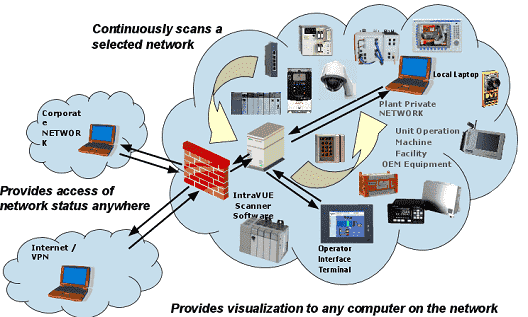
![]() The IntraVUE™ host should be inside the same subnet as the edge devices for best results without a firewall in-between. The IntraVUE host should always be connected to a (layer 2) managed switch to obtain SNMP data!
The IntraVUE™ host should be inside the same subnet as the edge devices for best results without a firewall in-between. The IntraVUE host should always be connected to a (layer 2) managed switch to obtain SNMP data!
Scanning Scenarios
Simple Network: The simplest network in which all the edge devices and all the switches are in the same subnet (e.g. scan range 192.168.0.1 - 192.168.0.254). To scan this type network you only have to enter the full scan range and proper SNMP communities. If this is your network, you do not have to read the rest of this document. IntraVUE was designed for this type network when the subnet mask is 255.255.255.0 (Class C) and there is not router required. Each 'cloud' represents different 'physical' plant zones, but all devices are pingable from the Top parent which is the IntraVUE host.
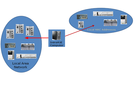
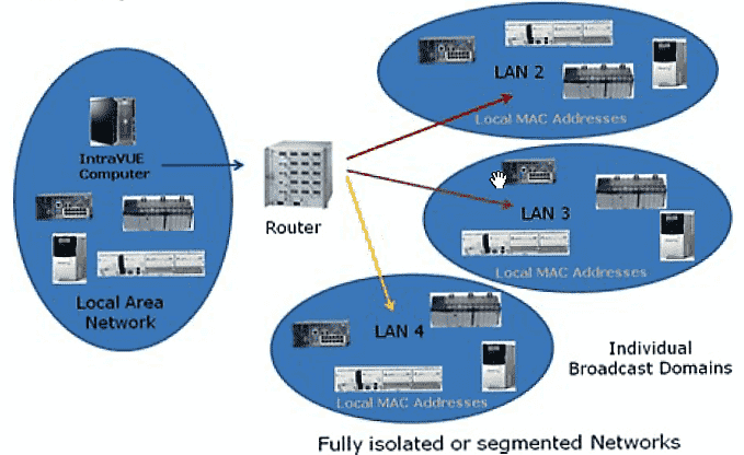
Multiple LANs from a single IntraVUE host using a router in between. Another simple network is one in which all the edge devices are in one subnet and all the infrastructure switches are in another subnet. The IntraVUE Server should be in the subnet of the edge devices and should be the top parent of the IntraVUE network. The IntraVUE Server is on the left scanning all the LOCAL edge devices communicate without going thru a router. However, the IntraVUE Server must go through a router in order to get ping and SNMP data from the switches to the remote networks. The router (which knows the macs of the switches) must be in the scan range of the same IntraVUE network and respond to the same SNMP read-only community configured in IntraVUE. See Configure Menu - Scanner Tab.
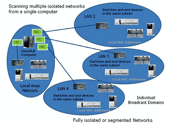
Multiple NIC cards and No Router or SNMP: In some cases, plant personnel are not allowed to know the SNMP community of the central router or access switch. In the next figure, a NIC card has been added for each formerly remote LAN to solve this problem. Now those LANs have local addresses on the host computer and communication does NOT go through the router. The MAC addresses of all devices are in the host computer local ARP cache. This configuration is also useful when IT departments isolate private LANs using VLANs or a firewall and SNMP is not allowed to go through. The use of Virtual Machines where the IntraVUE agent can be installed to scan those private LANs or VLANs solves this problem. However, if the number of virtual machines using IntraVUE agents is over whelming or costly to manage, we recommend instead using IntraVUE appliances installed as agents within those private LANs or VLANs. See Using the IntraVUE Appliance as an Agent and IntraVUE Appliance Configuration for more details.
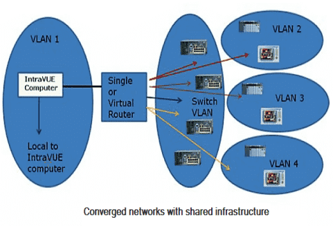
Networks using VLANs: is made more complex by configuring the layer 2 switches in the network to have VLANs. This is one of the most common plant floor network architectures. There are 5 VLANs. The layer 2 switches are in the center circle, Switch VLAN. Even though they are connected by layer 2 switches, devices in one VLAN can not communicate with devices in another VLAN without going through the router. For IntraVUE to provide the most diagnostics, each VLAN of edge devices should be a separate IntraVUE network in the System Configuration Scanner Tab. Each one of the 'remote' networks must also include the interface (Gateway IP address) of the router leading to the edge devices (as determined by DOS command TRACERT) as the top parent. In the next figure, the IntraVUe network for VLAN 1 needs to have the local computer as top parent, all the local IP addresses, the router, and the switch IP Addresses. VLANs 2, 3, and 4 each need to have the IP address of the router as top parent, the IP addresses of the VLAN, the router, and switch's IP addresses all in the scan ranges of that IntraVUE network. (The switch's IP addresses will be in all 4 IntraVUE networks.) VLANs are configured in a layer 2 switch by assigning VLAN numbers to ports of the switch. Packets arriving on a port of a switch having a VLAN(s) configured will only be sent to other ports having the same VLANs configured. This limits broadcast traffic to only the ports with the same VLAN number as the originator.
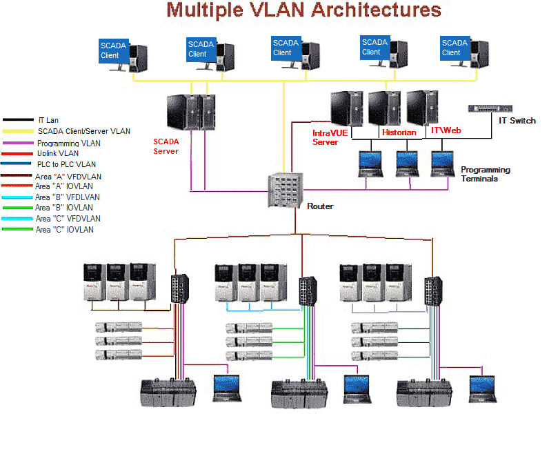
Multiple VLANs: using different colored lines for each VLAN. If the destination MAC is on a port in another VLAN, the message will be sent to the gateway and then back to the switch on the port having the same VLAN number as the destination. If a port of a switch is not configured for a VLAN, it acts as if all VLANs are configured for that port. All traffic for a device in a different VLAN (different colored line) must go to the router to be redirected to the switch.
Implementing Rapid Spanning Tree protocol (RSTP) in the switches creates a physical ring of communication where the last switch in a series of connected switches is connected to the first switch, thus forming a ring. The last link is never 'active' unless there is a break between any other switches in the ring. At that time, communication will start a new path and all switches will continue to be able to communicate, but using a different path. Nothing special needs to be done to handle this situation. IntraVUE will discover the new path and redraw the topology to reflect the change in the ring.
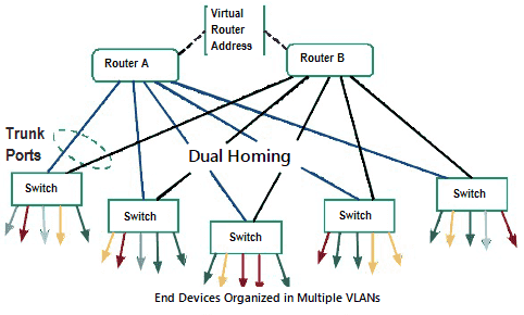
Hot Standby Redundant protocol: (HSRP) creates a connection between a pair of routers. In this scenario 2 routers are configured so that either one can act for the other in the event the other router fails. The routers 'share' a virtual IP address and a virtual mac address as well as having their own ip and mac. In some cases, one router will respond to the virtual IP/MAC Address, but the other can assume in within milliseconds if necessary. In many cases, each router handles some VLANs. Router A will handle the even VLANs and router B will handle the odd VLANs. Other devices are configured to use the 'virtual' IP address of the routers. Additionally each 'upper level' layer 2 switch is connected to both routers, so that if a router failure happens there is a connection to the other router using the same 'virtual' IP address. Since the routers are connected and the upper switches are connected to each router, an alternate path is created and the mac of the routers can be seen on two possible ports of the 'upper level' switches.
Isolated Networks behind a Gateway, PLC, Private VLANs, Firewalls, NATs
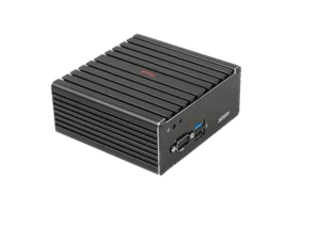
The IntraVUE Appliance is a small-factor headless appliance strategically placed in a network closet at a remote site with the purpose of scanning edge devices in one or multiple cases below:
1. Devices in an isolated network behind a gateway. A switch inside the 'isolated network' behind a gateway using one port of the agent and the other port of the agent is connected to a switch on the 'plant' side (or plant VLAN Access) network.
2. Private VLANs. One is the private VLAN of the 'system' and the other provides access from the 'plant' to the PLC of the 'system'. The IntraVUE Agent has one interface connected to a 'system VLAN' port of the switch and the other agent's Ethernet interface is connected to a 'plant VLAN' port of the same switch.
3. If a NAT, or Firewall Access to the NAT, or Firewall devices is configured to send all packets from an IP address on the plant side to the IP of the IntraVUE agent on the 'system' side of the NAT/Firewall, then the IntraVUE Agent can scan the devices behind the NAT, or Firewall.
Using IntraVUE Appliance as an Stand-alone Server to scan the Plant Network:
When there is no physical server or virtual machine available, the small-factor headless appliance can be deployed as an IntraVUE Server. The only differences is that it does require software registration and only one port of the appliance is connected to a switch on the 'plant' side.
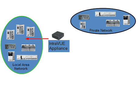
See Using the IntraVUE Appliance as an Agent and IntraVUE Appliance Configuration for more details
Install / Upgrade and Register IntraVUE™ 3
Installation or Upgrade Instructions of IntraVUE™ full version for Windows Based Systems
![]() Before you install or Upgrade IntraVUE you will need to have an active support contract or active IntraVUE subscription before you can register your Product Key (PK). The IntraVUE Web registration portal will reject your PK if your do not have either requirement. You will need to contact a distributor near you to renew either one.
Before you install or Upgrade IntraVUE you will need to have an active support contract or active IntraVUE subscription before you can register your Product Key (PK). The IntraVUE Web registration portal will reject your PK if your do not have either requirement. You will need to contact a distributor near you to renew either one.
- Download the latest Intravue_.x.x.exe installer. See Downloads
- Right-Click Click Intravue_.x.x.exe and select "Run as Admin"
- Click "Next" for on the Welcome to the IntraVUE Setup Wizard screen
- Click "I Agree" to the License Agreement.
- Select "Install" for Choose Install Location. Default location is set to C:\intravue but you can change.
- If you're upgrading, you will receive a notice to make a backup of your current database. Click “OK” to continue with the upgrade.
IntraVUE will make a backup of the appropriate folders and store them automatically in “prevxxxx” folders under C:\intravue when you run an upgrade.
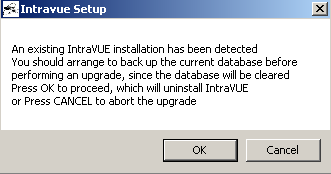
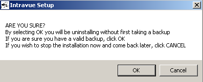
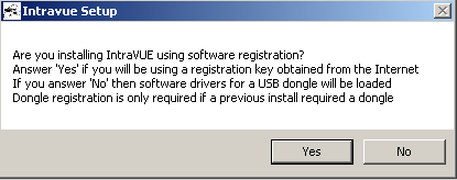
- Select “Yes” to use IntraVUE™ with a software license key. If you purchased an IntraVUE USB dongle select "No".
![]() This question is used to determine where IntraVUE should look for licensing information (c:\intravue or from a USB dongle)
This question is used to determine where IntraVUE should look for licensing information (c:\intravue or from a USB dongle)
-
A Java Setup - Welcome window appears whenever java is not installed in the machine. Click "Install" and let the Java Install run its course.
 Java 32-bit will be installed as part of the installation. If the version of Java is outdated Java prompt you to remove Out-of-Date version. The UI does not make use of Java 32-bit, but it's only used the for the scanning engine.
-
Click “Next” at the “Restore Java security prompt” when asked.
-
Click “Close” to finish the Java installation
-
![]() JAVA might prompt you to update. Ignore as IntraVUE™ will install a 32-bit version of Java
JAVA might prompt you to update. Ignore as IntraVUE™ will install a 32-bit version of Java
- Close the “Verify Java Version” Internet Browser.
-
Click “Yes” to “Do you want to launch IntraVUE™ Browser”
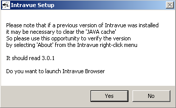
- Once the browser window launches, if you get IntraVUE™ logo at the top your installation performed successfully.
- You can Open IntraVUE™ in any compatible browser such as IE 11, Chrome or Firefox. See for details.

![]() Pay close attention to the following issues that might prevent you from opening up using IntraVUE™ correctly.
Pay close attention to the following issues that might prevent you from opening up using IntraVUE™ correctly.
- Ensure the IntraVUE 3 URL (http://127.0.0.1:8765/Iv3/) is showing in the URL address bar and is in trusted sites on the security tab of IE's Tools > Internet Options (uncheck 'only use https'). This helps pop-up dialogs appear.
- If you are being redirected to the old URL http://127.0.0.1:8765/iv2/ivue.jsp in Internet Explorer you either have an IE version earlier than v11 or you need to reset your browser settings from >Tools > Options > Advanced > Reset Internet Settings and reboot.
- In the Windows services (Start > Run > services.msc) make sure the services are running: 'Apache Tomcat etomcat', 'Auto-Ip Server', 'Autoip Ping Daemon', 'Mysql'.
- If you get a white/blank screen when you browse to IntraVUE in Internet Explorer, remove 127.0.0.1 (or IntraVUE host's ip address) from the websites listed under Tools > Compatibility View Settings > "Websites you've added to Compatibility View".
- It is required to install the included 32-bit Java JRE included with the IntraVUE software install since the IntraVUE Scanner does not support running on 64-bit Java JRE.
- We recommend you set Java to NEVER update. IntraVUE software does not support 64-bit Java.
- Microsoft Windows update could stop some services from fully starting. The IntraVUE services will try to restart themselves for about 3 minutes but the Microsoft messages such as "please do not turn off the computer while updates are applied" stop some of the IntraVUE services from starting. In the Windows services (Start > Run > services.msc) start these services if they are not running: 'apache tomcat etomcat', 'autoip ping daemon', 'mysql'.
![]() See New Installation for more installation details
See New Installation for more installation details
Registration or Upgrade of IntraVUE™ Product Key
![]() If you are registering or updating an IntraVUE dongle proceed to 'Register IntraVUE when using a dongle' down below.
If you are registering or updating an IntraVUE dongle proceed to 'Register IntraVUE when using a dongle' down below.
-
Invoke IntraVUE™ from your desktop or open an internet browser and enter http://127.0.0.1:8765 in the address bar if IntraVUE is installed on the same computer, otherwise change 127.0.0.1 to the IP address or URL of the IntraVUE host. Press Enter.
- Click > Configure > Login as user "admin" > password "intravue".
- The Registration link will immediately appear.
- Copy the KEYCODE number. You'll need this number in the next step.
- Obtain an IntraVUE registration code from the IntraVUE User Web-Based Registration by clicking "here" next to "To get a registration code" or entering this address into a second tab https://intravuereg.panduit.com/intravue-registration/index.php
- Within the web registration form, Enter your Email Address, Organization, KEY CODE, PRODUCT KEY and SERVICE CODE (As Provided by Panduit with your purchase). Click "Submit Query".
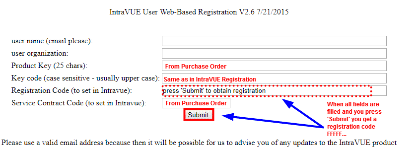
- Copy the returned “Registration Code” (e.g. FFFF...) into the Registration Code field in the IntraVUE's "REGISTRATION" page. This activates IntraVUE™ to enable monitoring of Automation Networks.
- Copy the "Product Key" into the "PRODUCT KEY" field in IntraVUE's "REGISTRATION" page. This activates the IntraVUE product itself.
- Copy the “Service Contract Code” into the “SERVICE CODE” field in the IntraVUE's REGISTRATION page. This activates the KPIs system and other add-on features of IntraVUE™ provided for customers under Support. If target software is not currently under support, the “Service Contract Code” field will remain blank.
- Click 'Submit Registration'. At the top of the REGISTRATION page should show something “Your registration has been completed successfully”. If it does not call Tech Support.

![]() Your Product Key might be rejected by the web registration system for several reasons. See this knowledge base article for more details: KB4473
Your Product Key might be rejected by the web registration system for several reasons. See this knowledge base article for more details: KB4473
![]() Make sure there are not trailing blank spaces as this will prevent the IntraVUE™ User Web-Based Registration from completing your request successfully.
Make sure there are not trailing blank spaces as this will prevent the IntraVUE™ User Web-Based Registration from completing your request successfully.
Register & Upgrade IntraVUE™ by entering license information (dongle-only)
- If you selected 'No' (for using a USB dongle) during the initial IntraVUE installation, plug the IntraVUE Dongle into the machine now.
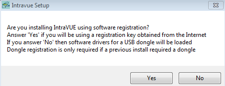
![]() Dongles are shipped without registration. They are registered the same way as Software Product Keys. The Dongle will show up having a key code starting with 999xxxxxx. If you do not see that, then the dongle is not recognized. You may have answered Yes to # 1 above. Try re-running the install and answer 'No'. If the problem persists contact Tech Support.
Dongles are shipped without registration. They are registered the same way as Software Product Keys. The Dongle will show up having a key code starting with 999xxxxxx. If you do not see that, then the dongle is not recognized. You may have answered Yes to # 1 above. Try re-running the install and answer 'No'. If the problem persists contact Tech Support.
- Follow steps 1-10 from above (i.e. Registration & Renewal non-dongle)
- Message "Invalid Service Contract code" will change to

Refer to the dongle steps for an alternate dongle registration & update process
Completing Initial Configuration
