Creating Plant Documentation
Current device documentation does not reflect an up to date view of the plant network and a logical view makes it hard to keep up with relevant changes. These steps allow you to create current and relevant documentation for the IntraVUE plant network in logical format as well as in paper format.
-
Open a browser and go to http://127.0.0.1:8765. Change 127.0.0.1 to the address of the remote IntraVUE host as necessary.
- Click on any device. A slider bar will pop up on the right on the screen. This is your device properties panel.
![]() If you haven't Admin Verified such devices click "Admin Verify". See Admin Verification in IntraVUE 3
If you haven't Admin Verified such devices click "Admin Verify". See Admin Verification in IntraVUE 3
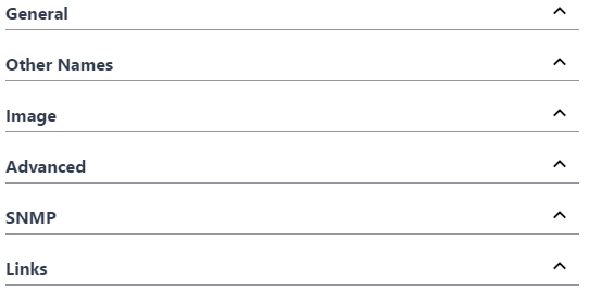
- While logged in as admin click "Edit". The Device Configuration dialog has 6 sections that allow you to configure the unique properties of a device.

- In the General Tab > Set a defined device name and location.
- In the Other Names tab > Set additional defined names (i.e. function, description, owner ).
- In the Image tab > Assign an image from the drop down.
- In the Links tab > Fill in any documentation link (e.g. Administration Web link, Floor Layout, Maintenance user manual, wiring diagram, location pictures, various devices properties) for each URL NAME box that wasn't auto-detected by IntraVUE.
- Click " Apply and Close"
 Remember to save your changes before clicking on a different device as your changes will not be saved automatically.
- Continue doing this for all end devices, switches, and the top parents (i.e. router, IntraVUE™ agent, and the IntraVUE™ host).
| Tab | Description |
|
General |
Contains Admin Verification, wireless, SNMP, email, and other settings. See Device Configure - General |
| Other Names |
Allows you to set other devices names in the devices properties. See Device Configure - Other Names |
| Image | Allows you to assign an image to a device. See Device Configuration - Image |
| Advanced | Allows you to change device type and behavior on the map view. See Device Configuration - Advanced Tab |
| SNMP | Allows you to enable or disable SNMP requests to a device. See Device Configure - SNMP |
| Links | Allows you to assign Web Links to a device. See Device Configure - Links |
![]() Refer to Side View in Edit Mode for detailed explanations for all device properties
Refer to Side View in Edit Mode for detailed explanations for all device properties
Import & Export Functions - CSV File
When you look at the exported data in a spreadsheet program you will find many columns. There are 3 basic sections:
- Reference data
- Configuration data for each IntraVUE™ 'View'
- Configuration data from the device's General Tab
- When saving the file, use CSV as the type and use quotes as the field marker. Don't use quotes in any view names.
Although the export function outputs many columns, you may delete columns you are not interested in EXCEPT the ipAddres, ref, and parentRef columns. These are used during the import process. You may not change any values to the left of DeviceName. They are shown in the image below.

- IP - IP Address or n/a if the line represents an auto inserted node.
- Active - 1 if the device is currently connected.
- MAC - MAC Address.
- Ref - internal database reference number.
- ParentRef - internal database reference of the device's parent.
- ParentIP - The IP Address of the device's parent. This will be a switch, router, or the top parent of the IntraVUE™ network.
- ParentPort - The port number from the parent to the device.
- UlinkPort - If the parent is a switch, the uplink is the port leading back to the top parent, otherwise it is 0.
It is particularly useful to SORT the exported data by the ParentIP column and then by the ParentPort column. This will give you a list of all your devices arranged by the switch they are connected to, in port number sequence. This is very useful if you want to compare what IntraVUE™ says to what your documentation says.
The next section contains contains columns for names, weblinks, and images. There is one sub-section for each of the 6 views of IntraVUE™. Note there is no column for IP View Name because you can not change that.

- xxxViewName - The name to appear for this view.
- xxxViewWeblink1Title - name to appear to user in the browser.
- xxxViewWeblink1URL - url that will be called when the user clicks on the link.
- xxxViewWeblink2Title
- xxxViewWeblink2URL
- xxxViewIconImage - icon image to display for this view
- xxxViewThumbnailImage - thumbnail image to display for this view
The last section contains items from the Device Configuration General Tab.

- Category
- Auto Connect
- AutoBootp
- IsWireless - this corresponds to the WAP checkbox.
- Send Alarms - to 'this' device's specific recepient.
- AlarmEmailAddress - email for 'this' device's specific recepient.
- SendToDefaultUser- to email alarm recepient in the System Configure Email tab.
- Verified - Admin Verified checkbox.
- Properties - An encapsulation of several items on the Device's General Tab. This column is not meant to be edited. It is meant to be copied from one device configured the way you want to another device without modification. This includes columns such as 'disable all snmp', 'ignore bridge mib', 'use snmp for mac', and snmp community.
- PKI.critical - This column is only available when you have enabled critical status for the KPI System on at least one device. See Device Configure - General
See CSV Column Values for a list of available values for selected columns
Refer to Export / Import for more options
With this new feature you are able to manipulate the Topology view of your network to your individual requirements, draw individual zones or "containers" to re-arrange your network, and print the entire plant layout with or without a background plant diagram in various sizes. This steps requires you already have IntraVUE™ scanning a network (see Completing Initial Configuration).

Follow these steps to print a plant layout of your current plant network topology:
- Open a IntraVUE™ by going to http://127.0.0.1:8765 or https://127.0.0.1:8766 (when HTTPS is enabled) on your browser. Change 127.0.0.1 to the address of the remote IntraVUE host as necessary.
-
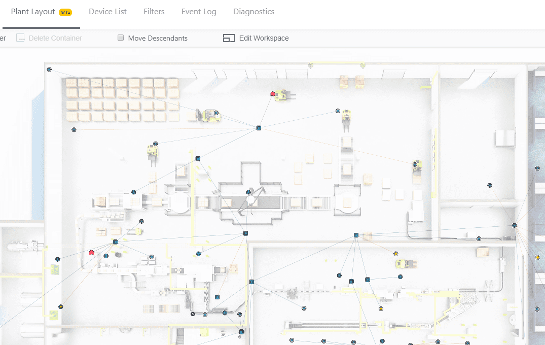
Click "Plant Layout"
- Click 'Login to Continue' to continue. Username 'admin' password 'intravue' is the default account.
- A 'Preview' appears. You have two choices
- Load a background layout image:
If you have a professional image (*JPG, PNG, or GIF less than 10MB) click "Choose File" and browse to the location of that image. Sample images are under C:\intravue\plant_layout
- Click 'Open' to preview the image.
- Click on "Select a Size" (see that chart in step 9 below to see the exact dimensions). ANSI D is the most popular.
- Click 'Submit' to apply an image to the Plant Layout view
- Skip loading an image: Click "Cancel" and go to # 5.
- Load a background layout image:
- The Plant Layout has multiple Functions and Settings
- You can zoom in and out by using your mouse roller or by clicking the view controls on the far left bottom of the screen.
- You can move the entire topology to include areas outside of the screen area by dragging the topology with a left-click hold with your mouse.
- You can move any node around a 365 degrees motion by doing a left-click hold with your mouse and drag the node.
- To move a parent node and children:
- Hold both the C-trl and 'x' keys and do a left-click hold with your mouse to draw an area around the devices you want to move. The devices in the drawn area will be highlighted. Do a left-click + hold drag to move the selected devices to the desired location.
- OR. Click setting "Move Descendants" and simply left-click hold drag the parent node and children to the desired location. Uncheck this option to prevent nodes with children to be moved accidentally.
- You will see that the connection lines disappear while moving the device.
- Plant layout comes with containers that you can use to specify which devices are in a different zone in the plant (e.g. a different floor, room, or cabinet). To create containers:
- Click "Add Container". The label will turn blue
- Hold the Ctrl key and click + drag the left mouse diagonally to draw a container around devices. You will be prompted to provide a name for the container before it can be created. You can create more containers while the "Add Container" option is enabled.
- To expand, or shrink a container by doing a single left click on it and resizing it. To move a container, click on the "Add Container" button. The button will turn back to black color.
- Subsequent containers will be numbered in sequence starting with "Area 1".
- Double click on a container to automatically zoom in.
- To delete a container click do a single left click and then click "Delete Container". Repeat this step to delete subsequent containers.
- To replace or remove the background image:
- Click on "Edit Workspace"
- Click 'Remove' to remove the background image. The Preview will become blank.
- To have a blank background select a size and click 'Submit' without choosing a file.
- To pick another background image click "Choose File", select a size, and click 'Submit'
- Device position and containers will be automatically saved to the currently used IntraVUE database and are available if you copy the database to another IntraVUE™ host. You will have to repeat step 4 above if you want to see the same plant layout on a different IntraVUE™ host.
- A "New Changes Applied" banner in green letters will appear on the left side of the plant view constantly as you make changes. If you tab over to the Topology view and back you will notice the changes are saved.
- The plant layout can be printed in both ANSI (American) paper sizes or ISO A0-A4 (International) paper sizes.
Size Width x Height (mm) Width x Height (in) Closest ISO ANSI A 216 x 279 mm 8.5 x 11 in A4 ANSI B 279 x 432 mm 11 x 17 in A3 ANSI C 432 x 559 mm 17 x 22 in (Requires a Plotter) A2 ANSI D 559 x 864 mm 22 x 34 in (Requires a Plotter) A1 ANSI E 864 × 1118 mm 34 × 44 (Requires a Plotter) A0 ISO A0 841 x 1189 mm 33.1 x 46.8 in (Requires a Plotter) ANSI E ISO A1 594 x 841 mm 23.4 x 33.1 in (Requires a Plotter) ANSI D ISO A2 420 x 594 mm 16.5 x 23.4 in (Requires a Plotter) ANSI C ISO A3 297 x 420 mm 11.7 x 16.5 in ANSI B ISO A4 210 x 297 mm 8.3 x 11.7 in ANSI A - Print Plant Layout. To print the layout you have two options:
- Print from Browser:
- Hit the Ctrl + P keys
- Select the desired paper size on your printer options. See step 9 above. Click 'Print'.
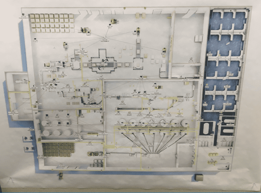
- Your final plant layout should look something like this
- Visio Export + Print:
- Make sure you have the Visio package installed (i.e. Visio 2013 or 2016)
- Download the IntraVUE Plant Layout Export Tool (IntraVUEPlantLayoutExporter.msi). Run the installer and follow all prompts.
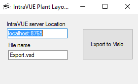
- Open the Plant Layout Export Tool from Start > Programs > IntraVUE Plant Layout Exporter

- Change the 'localhost:8765' to be x.x.x.x:8765 when running IntraVUE™ remotely. Change the File name as necessary and click "Export to Visio"
- Wait for the Plant Layout too to change from "Processing..." to "Export Completed Successfully" and click on the 'x' to close.
- Open the *Export.vsd file. It should look something like the following image:

- Hit the Ctrl + P keys
- Select the desired paper size on your printer options. We selected ISO A0 for this example. See step 9 above. Click 'Print'
- Mount this plant layout on a wall or provide to your integrator.

- Print from Browser:
