

1 Table of Contents
2.1 Functional Overview
2.2 System Requirements
2.3 IntraVUE Placement
2.4 New Installation
2.5 IntraVUE's 6 Views
2.6 User Types and Security
3.1 Main Screen
3.2 System Menu for Users
3.3 Device Menu for Users
3.4 Icon Images
3.5 Thumbnail Images
3.6 Use of Color in IntraVUE
3.7 Roaming Devices
3.8 The Hover Feature
3.9 Device Properties
3.10 Device Threshold Line Graphs
3.11 Multiple Device Threshold Graphs
3.12 Event Log
3.13 Search Dialog
3.14 SNMP Data Dialog
4.1 System Menu for Admins
4.1.1 Create System Archive
4.2 Admin Login
4.3 Device Menu for Admins
4.4 System Configuration
4.4.1 System Config - General Tab
4.4.2 System Config - Database Tab
4.4.3 System Config - Threshold Tab
4.4.4 System Config - Scanner Tab
4.4.4.1 VLANs - Virtual Local Area Networks
4.4.4.2 Selecting the Top Parent
4.4.5 System Config - Email Tab
4.5 Import and Export
4.6 Device Configure
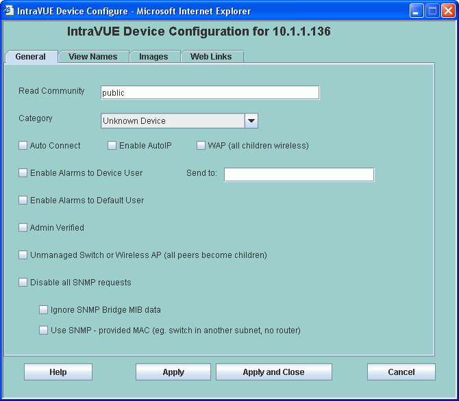
4.6.1 Device Configure - General Tab
4.6.1.1 Admin Verification
4.6.2 Device Configure - Names Tab
4.6.3 Device Configure - Images Tab
4.6.4 Device Configure - Weblinks Tab
4.7 Manually Moving Devices
4.8 Configuring WAPs and Unmanaged Switches
4.9 IntraVUE File System
5.1 Database Upgrade
5.2 Using the IntraVUE Agent
5.3 Custom Views and Links to the Intravue Browser
5.4 ivserver.properties File
5.5 The ivserver.xml file
5.6 Handling Trunking in Switches
5.7 How to Add an additional web server Port Number
5.8 Product Key Upgrade
5.9 Read Me
5.10 Legal Trademarks
-1 Other Languages
Section 1
Please read Upgrading if you had IntraVUE 1 previously installed.
Video Help files are contained on CD 2 of the IntraVUE installation CDs. They are also available for downloading.
A User Forum for IntraVUE is at http://www.NetworkVisionSoftware.com/forum The forum contains additional help, facts, and tools. Users with Service Contracts may post questions and download updates. Product Overview And Installation
Video Help files are contained on CD 2 of the IntraVUE installation CDs. They are also available for download at http://i-vue.com/intravue/IntravueCD2.iso Note this file is over 200 MB and may take some time to download.
The download is in the form of a ISO file which can be burned onto a CD. After downloading, use the directions for your CD burner to create a CD from the ISO-9660 image file. The result is exactly the same as CD 2.
Section 2.1
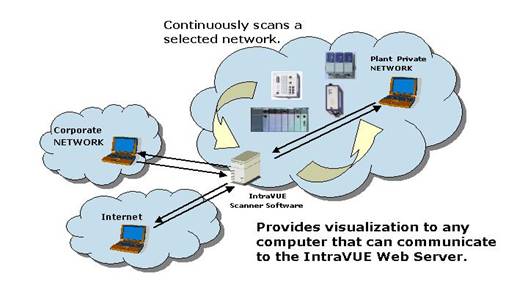 IntraVUE continually scans the network to determine if new devices are added
and if currently installed devices are disconnected or moved.
This dynamic capability is enhanced when managed switches and routers are used in the network infrastructure.
IntraVUE is made up of several distinct and integrated components:

Section 2.2
Section 2.3
Section 2.4
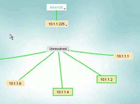 As soon as a device responds to a ping it is placed under the Unresolved Devices node and the individual nodes.
During this period IntraVUE first attempts to find MAC address information from the top parent and any local routers.
One cause of IntraVUE not determining the MAC address is an incorrect SNMP community setting in IntraVUE for a router.
Once the MAC address has been determined, IntraVUE attempts to find the correct location in the network hierarchy to place the device.
If the IP of the device is in the same subnet as the top parent it will be moved to the top parent pending a move to a managed switch.
If it is in a different subnet from the top parent of that Intravue network, it will remain in unresolved unless a router having an interface for that IP is discovered
or a managed switch claims its mac address on a port. In those cases the device will move out of unresolved.
This situation could occur due to an incorrect community in a router or switch, or its switch is not in the scan range.
Devices under the Unresolved node will have all the functionality of other devices in IntraVUE.
The Unresolved node serves as a placeholder for devices that can not be properly placed by IntraVUE with some information indicating the difficulty.
Accessing SNMP data from the configured routers and managed switches, IntraVUE starts to automatically build the connection information of these devices.
This establishes the parent-child relationship. A parent is a device that has other nodes/devices connected to it.
IntraVUE gets hierarchy information by SNMP queries to managed switches. If the community for a managed switch is incorrect or not the default, IntraVUE will be unable to determine the device is managed and the hierarchy will appear to be flat.
There are, however, cases in which unmanaged switches or hubs have been utilized. If the scan engine discovers two or
more devices on the same port of a managed device, the scan engine will assume a hub or unmanaged switch (without IP) is present
and automatically insert a node. These nodes will be given a device name of "Auto Inserted Node" and should be edited to describe the actual device.
Provisions in the IntraVUE software have been made for other devices to be manually added and to manually move devices to them.
The ability to add and move devices is covered in ManualMoves.
Section 2.5
Section 2.6
Section 3.1
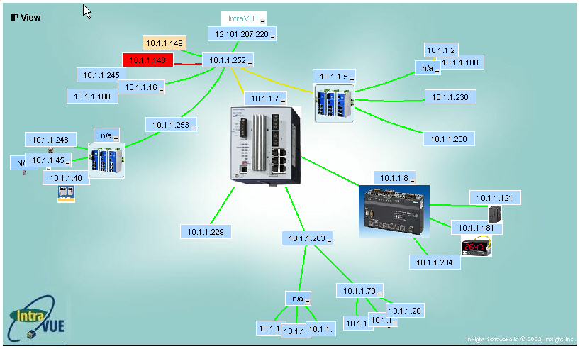
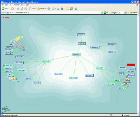 The initial browser view of IntraVUE shows the organization of all devices within each configured network.
The IntraVUE user interface is provided thru a browser such as Internet Explorer or Mozilla Firefox.
On the host computer the URL can always be entered as http://127.0.0.1:8765.
From any other computer that can ping the host, you may see the same thing by substituting the
IP address of the host for the 127.0.0.1, for example http://192.168.1.55:8765.
Note: the colon and 8765 is required after the IP address and typically you must also enter the http://.
A video is available which covers basic navigation, colors, and operation IntraVUE.
The Top Parent of each network will be one node away from the "scanner" node at the center of the screen.
The network is visualized as a star or tree of devices radiating out from the "scanner".
This patented method is called a hyperbolic tree.
Individual devices or nodes are shown as colored rectangles connected by colored lines indicating the connection between the devices.
Drag all nodes on the screen by holding down the left mouse button until the part of the network you are interested in get toward the middle.
Attributes of nodes in the middle are largest and they gradually disappear as the approach the edges.
You can think of the IntraVUE visual display as a flat network diagram that has been wrapped around a ball, and you can see only part of the ball.
This graphical feature allows very complex networks to be displayed in a single window.
Mouse Commands
There are several special or short cut keys that may be used with the IntraVUE user interface.
Section 3.2
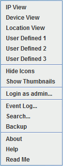 The second section allows the user to select the ability to show icons or thumbnails.
If the feature is enabled the button changes to allow the feature to hide the individual displays. See Icon Images or Thumbnail Images.
Note that the default view and whether icons and/or thumbnails should be visible can be set in the file c:\program files\intravue\autoip\ivserver.properties, see Special Settings.
The Login as Admin menu item allows the administrator to log in from any browser.
This function is password protected.
The Event Log item allows the user to access the event log for all devices.
When accessed from the system menu, the event log contains all activity for all devices.
Search provides the user with the ability to search the Network for a specific or a group of nodes based on IP, MAC,or a name used as one of a devices 'views'.
Backup allows a User to make a backuup without being logged in as an Admin.
This is useful when a problem occurs in the network and you want to preserve as much data as possible with the 3-6 hour threshold resolution.
About contains the details associated with the installed version of IntraVUE.
Help leads to the pages you are viewing now.
Readme contains release notes, future enhancements, errata, and other information that may not be in the printed documentation.
Section 3.3
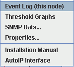 Four functions will always be present:
Section 3.4
Section 3.5
 Each View has a different Thumbnail assigned for each device.
For example in the Location View a picture of the enclosure with a arrow pointing at the device
will help in identifying the actual location of the unit.
This is very useful if there are several similar units such as Ethernet I/O blocks in the same enclosure.
In Device View the image could be a copy of the device from the manufacturer's web site..
Section 3.6
 Newly discovered devices and devices that have not been verified by the administrator appear in a light brown color.
 Once a device has been verified by the administrator the node will be blue.
A normal network should have all the device nodes in blue. If a new device joins the network it will be easy to spot the light brown box.
 If an Admin Verified device moves, the verified position will be represented by a red filled box (blue changes to red).
At the new location, a new, unverified node will be placed representing the actual location of a device. See AdminVerify for more details.
 A device that has never been detected to support SNMP has a black outline.
 A device which currently has SNMP communication with IntraVUE has a green outline
 If the last 2 SNMP queries timed out, the event will be logged and the device will get a red outline until SNMP is regained.
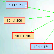 Nodes that have been selected with a left click have a heavy blue outline.
Notice the 10.1.1.106 in the picture above has lost SNMP and is NOT selected, the other nodes are selected.
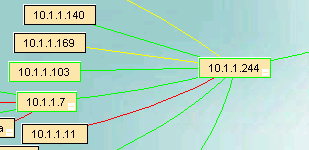 Five line colors are supported in IntraVUE.
Section 3.7
Section 3.8
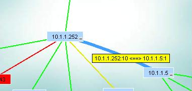 The hover text in the image above shows the connection between two switches. Switch 10.1.1.252 uses port 10 to connect to port 1 of switch 10.1.1.
Note: If the port numbers are misleading and you want to have other numbers appear,
see how the Trunking file works.
Note that routers are not connected by ports, so you will not see a port number in the hover text of connections to routers (unless it is a layer 3 device).
Hover text is also availabe when you place the mouse over a device.
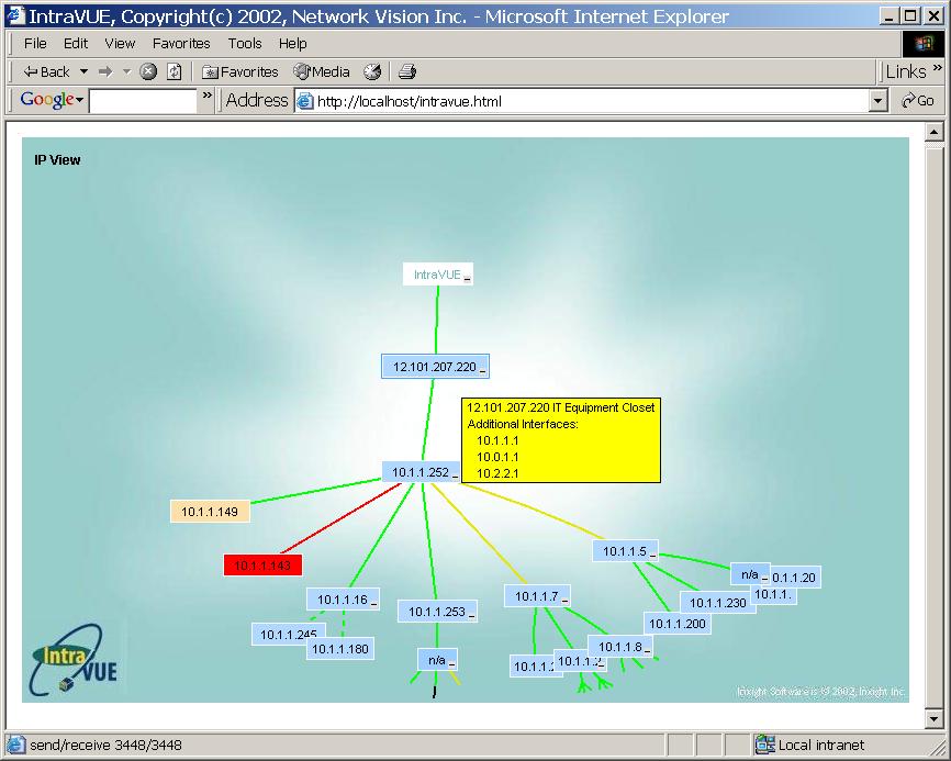 A hover over a device box will open a box with the ability to show any two of the six names defined by the six views.
In this example the IP and Location view names are selected for display. See setting device hover text.
Starting in IntraVUE version 2.1, a new feature has been added to allow you to add custom information as a second line to the hover text of a device.
This text is applied to the connecting line leading from the device toward the 'top parent'.
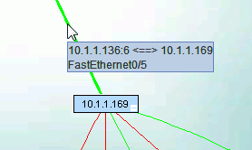 To add custom information do an Export. Using a spreadsheet program, the last column will have a label named 'Uplink.Doc'.
You may enter up to 255 characters in the field. The text will all appear on one line.
A Frequently Asked Question (FAQ) on the IntraVUE User Forum shows how to get better information from Cisco switches. See
http://networkvisionsoftware.com/forum .
Section 3.9
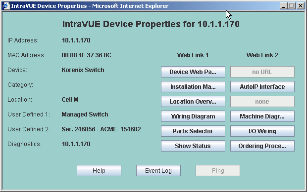 In addtion to showing the 6 view names, the MAC address and category of the device are shown.
For each device view, any web links that have been configured are available by selecting the appropriate button.
If a web link has not been configured, "none" appears.
If a web link name has been configured but no web link URL, "no URL" appears as in the example above for Location View, Web Link 2.
From the Device Properties dialog you may also go to the Event Log for this device.
The Ping button is currently disabled and is planned for removal. In IntraVUE 1.0 the
results of a DOS ping from the IntraVUE host were displayed. The current threshold graph
of ping responses makes this unnecessary. Depending on user feedback we may create a
high resolution ping graph showing ping responses every few seconds.
Section 3.10
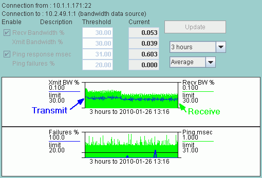 Enable or Disable Alarms
There are two checkboxes to enable or disable alarms for Bandwidth or Ping thresholds. These can only be changed by the Admin.
Both Ping and Bandwidth alarming is enabled in the above example.
Either transmitted or received data bandwidth can trigger a Bandwidth alarm.
Either exceeding the ping failure percent in the last minute or exceeding the ping response threshold in the last minute will generate an alarm.
Ping Data
Ping data is gathered 5 to 7 times a minute and the average of that minute is used as a single data point.
Any ping failures are recorded and the number of ping failures in that one minute is the Ping Failure Percent.
Bandwidth Data
If a device does not support SNMP, IntraVUE will try to get bandwidth information from the next higher switch of the device.
The device that provides the SNMP information is identified by (Datasource) on the Connection From/To lines.
Transmitted data is the data from the parent or 'from' device regardless of the data source.
Data Resolution
The data is stored internally in a way that progressively creates historical data from more recent data.
Over time data kept in seconds format is averaged to become minute format, minute data becomes 10 minute data, hour data becomes day data, and so on.
Below the Update button is the Time Scale drop down list. Selecting this control will display the following time intervals that may be selected:
Section 3.11
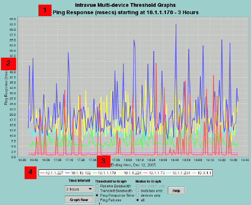 The small image above contains numbered markers for each of the major graph elemets.
The red 1 box is next to the Graph Title which includes the specific threshold currently displayed
and the time period of the data.
The scale of the data values is near the red 2. The scale changes each time new data is graphed
and is redrawn so the the maximum graph value is near the top of the graph.
The red 3 is near the time values for the graph. When displaying 3 hour data the values will be
the normal clock time. When displaying data for longer time periods there may be up to three lines
of time information. For instance, 12 month data will indicate the year, month, and day.
Note that the available data will fill the graph from left to right. If there is only a weeks
worth of data in the database and you select the 12 month view, the available data will fill the
x axis.
There will typically be an indication of the start and ending date/times in this area.
The red 4 shows where the graph legend is. Each device will have a color assigned to it. If
you have problems telling which line belongs to which device there is hover text near graph points
as well as a zoom feature (see below).
User Selection Options
 The Time Interval drop down list allows you to select between 3 hours of data and 12 months of data.
If data is not available for the entire period the time scale axis will be limited to the available
data. If you were to choose the 12 month option and IntraVUE had only scanned for one hour, no
data will be available.
The Max Devices To Graph edit box allows you to limit the number of devices that will appear in the graph.
The limit is based on worst case data. If 20 or less devices are graphed, a legend will be displayed under the graph.
Set the Max Devices to Graph to 21 or more and NO legend will be displayed.
You can select whether the graph shows Average Values for the data being graphed or Peak Values.
As data becomes older it is stored in fields that represent more information. One minute becomes 10 minute, becomes 2 hour, etc.
Intravue stores both the average of these periods as well as the maximum value for these periods.
This prevents a spike in a single minute from being lost when it eventually becomes 1 day data.
The Threshold to Graph radio buttons allow you to select amoung the four typs of graphs
The Nodes to Graph radio buttons allow you to filter data for only switches, only devices, all devices, or
if the current device is a switch, only the ports of the current switch. [Note this last option is
not available in the pre-release]
The Graph Now button gets new data from the IntraVUE database and displays the results.
Note: The graph does not update after changing selections, it only updates when this button is selected.
Hover Text
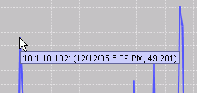 When the mouse is positioned near a graph POINT, not the line, hover text will indicate the IP Address of
the device and the time of the value.
Zooming in
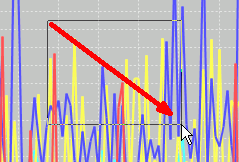 You can zoom in on any portion of the graph by dragging the mouse with the left mouse button.
To zoom in you must drag the mouse to the right and downward. As you drag you will see the
outline of the zoom area. When you release the graph will be zoomed.
You may zoom in as many times as you like.
Zooming out
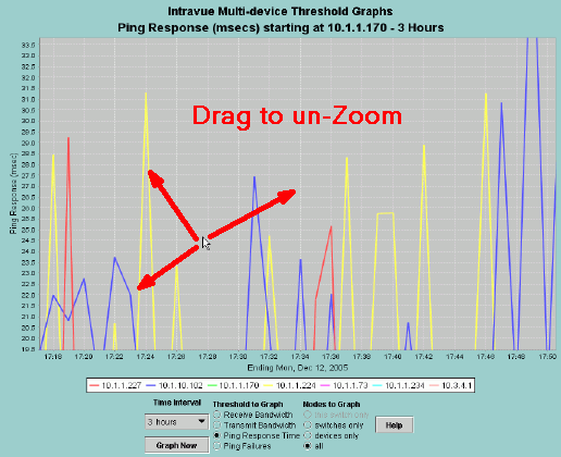 When you are ready to zoom out, simply drag the mouse in any direction except right and down.
Section 3.12
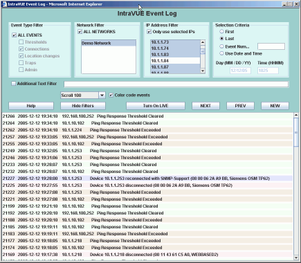
 The alternate view contains filtering controls to help you find exactly what you are looking for.
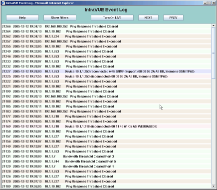
 IntraVUE continuously monitors all activity on the network.
To access the details of the entire network one opens the System Menu and selects Event log.
To access the details for a single device, the Event Log is selectable from the Device Menu.
Note: there is only one Event Log dialog. Once opened you can switch between all devices and just the ones you want to view by using the Only Use Selected IP's checkbox.
When the event log is initially launched, it defaults to the full view and no filters are set. In the full view you can navigate to other events by using the Next and Previous buttons.
You may also select the Turn on LIVE button to see events as the occur with a 5 second refresh.
Select Show Filters to change your selection criteria.
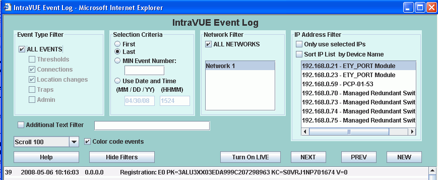 The Event Log filters allow you to filter events using several criteria
 If there are many different devices being displayed, you may select one device with a left click and additional devices holding the Control key.
A right click when one or more devices is selected displays a menu providing further options depending on what was selected. These options include:
Section 3.13
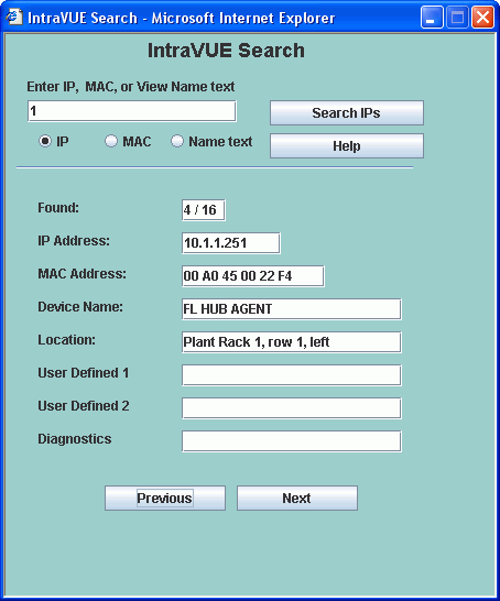 There are 3 radio buttons to select finding devices by IP address, view names, or by MAC.
When you change one of these buttons the text on the search button changes to remind you of your selection.
Below is the name search.
 Regardless of which type of search you use, the search is automatically prefixed with a wild card.
This means that a match will be found for everything that contains any number of characters before
the text you entered as search criteria.
For IP addresses there are several options.
Section 3.14
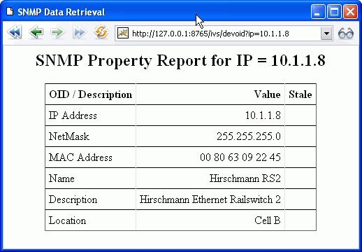 The first 6 lines, through Location, are standard MIB II entries
and are available from any device supporting SNMP.
Additionally the IntraVUE administrator can configure any other
SNMP data to be retrieved from the device and made available to
this dialog as well as to the Modbus/TCP interface of IntraVUE.
See Modbus and SNMP Configuration for more information.
Section 4.1
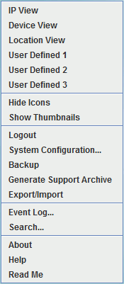 System Configuration provides access to the database and scanner setup options.
Backup will make a current backup of the database in IntraVUE's dbBackup folder.
The backup filename will be automatically generated based on the current date and time.
This is the same backup as in User mode.
Generate Support Archive
performs several actions. A regular backup is made.
Additionally a zip file is created containing the backup and a number of log and configuration files which will help technical support provide assistance.
Export/Import brings up a dialog which enables you to import data into or export data from IntraVUE.
Section 4.1.1
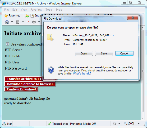
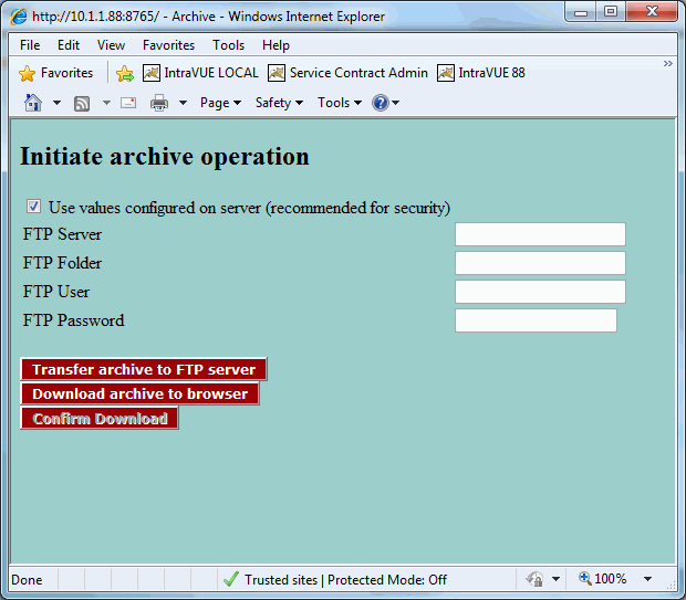 There are two main choices.
Section 4.2
<user username="admin" password="intravue" roles="admin,manager" />If security is any concern, please edit this file and change the password from the default of "intravue". Security is provided by limiting access to the IntraVUE host. With IntraVUE 2's remote administration capabilities, there is no need to have physical access to the host computer. The directories where security information is configured are not accessible from the web interface.
The Apache Tomcat web server that provides the user interface for IntraVUE can be configured to require a username and password before a user can see the IntraVUE web page.
The first step is to add security data to the file ...\intravue\AutoIP\tomcat5\webapps\iv2\WEB-INF\web.xml. Copy the lines below and insert them at the end of the file, just before the closing </web-app> line.
    <!-- Define a Security Constraint on this Application -->
    <security-constraint>
        <web-resource-collection>
            <web-resource-name>Intravue Application</web-resource-name>
            <url-pattern>/*</url-pattern>
        </web-resource-collection>
        <auth-constraint>
            <!-- NOTE: This role is not present in the defaugt users file -->
            <role-name>intravue</role-name>
        </auth-constraint>

    </security-constraint>
    <!-- Define the Login Configuration for this Application -->
    <login-config>
        <auth-method>BASIC</auth-method>
        <realm-name>Intravue Application</realm-name>
    </login-config>

    <!-- Security roles referenced by this web application -->
    <security-role>
        <description> The role that is required to log in to the intravue Application </description>
        <role-name>intravue</role-name>
    </security-role>

</web-app>  NOTE: do not copy this line.  Insert just before this line in the file
The above will require the user to login as the 'role-name' intravue. Role-names are defined in the file tomcat-users.xml, described above. The role 'intravue' is already defined in that file and has a username of intravue and a password of intravue.
If you are going through this process then you really want security that anyone reading this help file will not be able to break.
Therefore, you should edit the tomcat-users.xml file and add a new role. The two line below can be added to this file and will create a new role named 'remote' and this role will have a username of remoteUser and a password of intravue2
  <role rolename="remote"/>

  <user username="remoteUser" password="intravue2" roles="remote"/>
To complete the process edit the data in the lines in the sample above and change the lines starting with
Anyone logging in will now be required to use a username and password to login.
Note: You may create as many username and password combinations for the role remote as you like by adding additional <user.. lines to the tomcat-users.xml file.
Section 4.3 Section 4.4 Section 4.4.1 Section 4.4.2 Section 4.4.3 Section 4.4.4 Section 4.4.4.1
VLANs provide a means to group devices as if they were the only devices in a subnet.
VLANs are configured in Layer 2 switches.
Broadcast traffic within a VLAN is not broadcast to devices outside the VLAN
even if they are attached to the same switch. This is one of the main advantages
of a VLAN. It can shield devices from seeing the broadcast traffic of other devices,
including ARPs.
If two devices are attached to the same layer 2 switch but they are in different VLANs,
the physical traffic between the two devices must travel the path of the connected
cables from the layer 2 switch thru any other switches until it reaches a router,
which will then send the traffic back down the same wire to the original layer 2 switch.
There the traffic will go to the port of the device on the other VLAN.
A Power Point presentation, in html format, visually explains VLANs and IntraVUE.
(When you run the file chose Open with your Browser and then you must Allow Active Content when prompted.)
Section 4.4.4.2
Each IntraVUE 'network' is a grouping of logical devices depending on the
needs of the user. Each IntraVUE network consists of a set of scan ranges
and a Top Parent.
Only two devices can be a top parent: the host computer and a router for which the snmp community is known.
The Top Parent of an IntraVUE network is the device which can provide the MAC
addresses for the devices in the scan range.
Local: all devices in the same subnet as the IntraVUE host ip address.
Remote: all devices NOT in the same subnet as the IntraVUE host ip address.
Pings and other traffic to remote devices will leave the local subnet and go to the default gateway (a router) if one is configured.
The gateway will use its routing tables to direct the traffic to one of its interfaces or its gateway if it does not have an appropriate interface.
Again, the top parent of each IntraVUE network
is the device which has access to the MAC address information on the devices
that will be in its scan range(s).
The scanner will attempt to identify any routers that are in a scan range
and the scanner will try to get additional MAC addresses from any router
it finds.
If an IntraVUE network has some devices that are local and some devices that are remote, the host computer must be the top parent and
one (and only one) of the router's ip addresses should be in a scan range.
If you have VLAN's each VLAN should be in a separate IntraVUE network.
This will result in clearly showing the path traffic takes to go from one device to another.
If switches are in a separate VLAN, that IP address range can be added to each other VLAN's scan ranges.
Thus, each IntraVUE network will have the switches and show how devices are connected. Switches that
are not used in a particular VLAN can later be deleted from that IntraVUE network.
If there is one router and many VLANS and you want to scan those VLANs, make the same IP of the router
the top parent of each network. Each network would then have two scan ranges - one of just one IP for the router
and one for the range of devices EXCEPT the IP of the router in that range. For instance:
The purpose of the above is to avoid the scanner making unnecessary queries to the same physical router
when the router is going to respond exactly the same regardless of which ip/interface you use.
IF YOU ARE SCANNING ANY DEVICES LOCAL TO THE HOST COMPUTER the host is the
ONLY device which can be the top parent. This is because only the host
will have the MAC addresses for the local devices which the scanner is pinging.
(While the gateway router may know some of the MACs it will only know the ones
that communicate outside the local subnet.
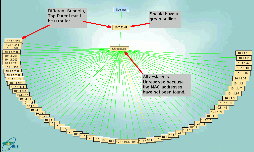
If the top parent is not the local computer, it must be a router because routers are
devices that tell mac addresses when provided an IP address. In the image, the top parent
is in an IP address range separate from the devices that are scanned. That is a
clue that the top parent must be a router.
In the image, there is no green outline
surrounding the top parent node. If the IP of the top parent IS a router, then the
SNMP community is not correct or the router has been configured with an Access Control
List and the IntraVUE host is not on the list.
If the top parent is not the local computer, it must have a green outline indicating
there is succssful SNMP communication with the ROUTER that knows the MAC addresses
of the devices in the scan range.
Section 4.4.5
Section 4.5
Although the export function outputs many columns, you may delete columns you are not interested in
EXCEPT the first 8, columns A to H. These are used during the import process. You may not change
any values in these columns. They are shown in the image below.
It is particularly useful to SORT the exported data by the ParentIP column and then by the ParentPort column.
This will give you a list of all your devices arranged by the switch they are connected to, in port number sequence.
This is very useful if you want to compare what IntraVUE says to what your documentation says.
The next section contains contains columns for names, weblinks, and images.
There is one sub-section for each of the 6 views of IntraVUE.
Note there is no column for IP View Name because you can not change that.
The last section contains items from the Device Configuration General Tab.
Section 4.6 Section 4.6.1
Starting at the top:
Read Community
This is the SNMP community to use in communicating with this device.
It MUST be correct for any managed switches in order for the topology to be discovered.
If it is not set for a switch, the switch and the devices connected to the switch will appear together under an auto-inserted node (n/a node).
This value will only be aautomatically set upon successful SNMP communication based on the value in the System Config Scanner dialog.
If you have many devices with non-default SNMP communities, you will be able to change the default in the Scanner dialog
for a short period and let devices with that community get discovered and configured. Then you
can change the community in the Scanner dialog back to the default.
Category
Cateogory allows you to pick the type of device from a list.
In Version 2.1 IntraVUE will automatically assign categories Router, Managed Switch, and PC.
All other categories must be assigned by the user.
(Currently the category field is not used by any other IntraVUE functions or reports.)
Auto Connect
This feature works in conjuction with Admin Verification.
Enabling this check box configures IntraVUE to treat this device as having permission to connect and disconnect
from the different parts of the network without creating 'ghost nodes' (see Admin Verified below).
Examples of this are wireless devices that roam a plant or test devices that move from location to location.
When a device with this feature enabled re-connects to the network it becomes active in its (perhaps new)
location without admin action.
Laptop computers and other equipment that can be connected at a number of different locations should also have this
feature enabled. The event log will still document all connections made and lost.
Enable AutoIP
Enabling this check box adds information about this device to a list of devices having IntraVUE's optional AutoIP BootP services.
AutoIP BootP server is a separate Software package that can be purchased to work with IntraVUE.
Please contact your local IntraVUE salesperson or go to http://www.intravue.net for more information.
WAP (all children wireless)
Enabling this check box causes any childrenn of this device to have a dashed line using the color that is appropriate for its line condition.
This is automatically checked if the device is discovered to be a Wireless Access Point.
Enable Alarms to Device User
If checked, any email alarms created by this device will go to the email address in the field ''Send To''
Send To
This field is the email of the user that gets email for this particular device. The ''Enable Alarms to Device User''
checkbox must be enabled for this to work.
Admin Verified
When this is checked, the position of the device is frozen or locked to its current position.
If the device is moved, the IntraVUE browser will show a red filled box at the verified position
and a tan box at the current location of the device. See a complete description about Admin Verification
and its benefits.
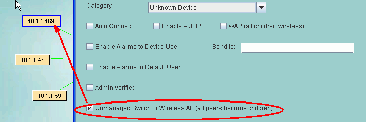
Unmanaged Switch or Wireless AP
The checkbox will cause all peer devices of this device to become children of this device.
It is provided as a convenience to using the MOVE function and works as new devices are discovered.
Wireless APs should also have the WAP checkbox checked.
A host computer with Virtual Machines can use this to make the VM sessions appear below the host PC.
Disable All SNMP Requests
This is used to stop poorly performing SNMP devices from filling the event log file with SNMP lost and gained messages
or to prevent SNMP to devices that would otherwise cause authentication traps to be issued
when the IntraVUE admin does not have access to its read only community.
Ignore SNMP Bridge Mib data
This is used for managed switches with poor snmp implementation.
It is typiically used in conjunction with the 'Unmanaged Switch or Wireless AP' checkbox.
Use SNMP provided MAC
This checkbox allows a the IntraVUE scanner to get the MAC Address of a switch in a different subnet
without having SNMP access to the router of that subnet. Many installations only have access to
their local devices but not switches in other subnets or the router that bridges the subnets.
Using thiss checkbox, the scanner gets the MAC address from the SNMP of the switch.
This only works for switches.
Section 4.6.1.1 Section 4.6.2
You can assign a name to be displayed for each View Name except for the IP View.
The IP View name is set when a device is initially discovered and it can not be changed, even the 'n/a' nodes.
If a name is not configured for a view, the IP address will be displayed inside a parenthesis
NOTE
This is important for some devices which respond to SNMP but do not have a name or location configured.
Check Ignore SNMP and then enter the value you want to use instead of what the device reports from SNMP.
Section 4.6.3
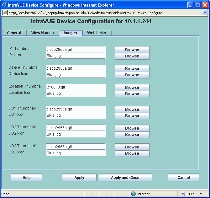
The Images Tab allows you to configure both thumbnail and icon images
for all views in one dialog.
Each view can have one thumbnail image and one icon image assigned to each device.
The display of the icons and images is turned on and off from the System Menu
or by a setting in the
ivserver.properties file
.
All images are assumed to be in the same file folder.
The name of the image file is case sensitive.
The default location of images is
c:\Program Files\Intravue\auotip\tomcat5\webapps\ROOT\intravue\images
Users frequently use digital cameras to capture pictures of devices in
the location and then assign those images to the Location view of a device.
Users also copy images from manufacturer or other sites to the image directory and link
those images to device views.
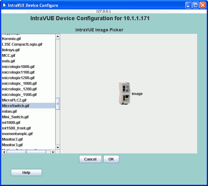
To help you select an image, each icon and thumbnail has a Browse button.
A list of all the available images (located in the default location) will be displayed
and you can browse through the images and select an image to use as a thumbnail or icon.
Section 4.6.4
2 web links can be assigned to each view for each device.
In the Title column enter what you want users to see when they right click on a device.
In the URL column enter the link to the page a view will see.
There are two types of web pages that can be put in the URL column, local pages to the host and remote pages.
If the file is on the IntraVUE host computer, enter the the relative path to the file starting at
IntraVUE's web browser home directory:
Copy or move the documents you want to add as web links anywhere in or below this folder. Feel free to create new folders.
In the example above, link 1 for the IP View is stored at
and the URL is entered using forward slashes instead of back slashes as shown below.
If a HTML document contains image files be sure to move them also.
(You may have to create additional folders to store images that are referenced by the HTML file in relative paths.)
The other type of web link is to a page on a different computer.
As long as the users browsing to the IntraVUE host also have access to the other remote computer,
you can link documents on other computers. In this case, enter the full URL to the linked page
including the http:// .
NOTE: Filenames are case sensitive, check the case if the link does not seem to work.
There is a setting in the ivserver.properties file that controls the
web link that is sent to the email receipient. This establishes the IntraVUE View that will be used
and whether icons and thumbnails should be on or off when the IntraVUE browser page opens. See the end of the file.
This setting can be superceded by settings in the URL used to browse to IntraVUE.
The weblink below will open the IntraVUE browser on the 10.2.3.44 computer in Location View with Icons off and Thumbnails on.
Uppercase I and T set Icons and Thumbnails on, lowercase i and t set them off. The view numbers are defined in the
ivserver.properties file.
This is particularly helpful when using the IntraVUE Supervisor edition.
Section 4.7
There are several occasions when you may want to manually change the relationship between the devices shown
on the IntraVUE browser dispaly.
When logged in as Admin, the Device menu provides two functions to accomplish the above: Add Child and Move.
There will be a black line connecting the new node.
It will stay black unless an IP device is moved under it.
The initial name of the new node will be 'N/A' (in caps to discriminate between automatically inserted nodes which are named 'n/a' in lower case).
To make a move, first select the device you want to move. It will get a blue outline.
While the device is still selected, right click on the parent device to which you want to move the device
and select Move. An event log entry is generated for this operation.
When doing this it is desireable to have the port of the managed switch be maintained.
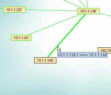
In the image below there is a port number for the line connecting the device.
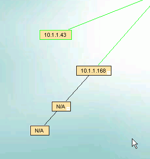
Use Add Child and add a child first to the device, and next to the just added child.
You now have two unnamed child devices under the original device.
Now Delete the device with the IP address.
It will be rediscoved and become a child under a NEW autoinserted node, at its original location.
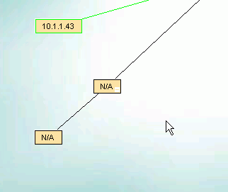
Next select the device (it gets a blue outline) and use Configure on the lowest child to MOVE the device below that node.
The auto-inserted node will go away, the connecting line to the first node will still have a port number, and the
additional device nodes will help you understand you network when problems arise.
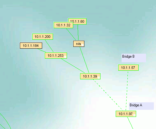
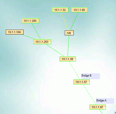
The devices on the other side of the bridge will appear under the top bridge, along with the other end of the bridge.
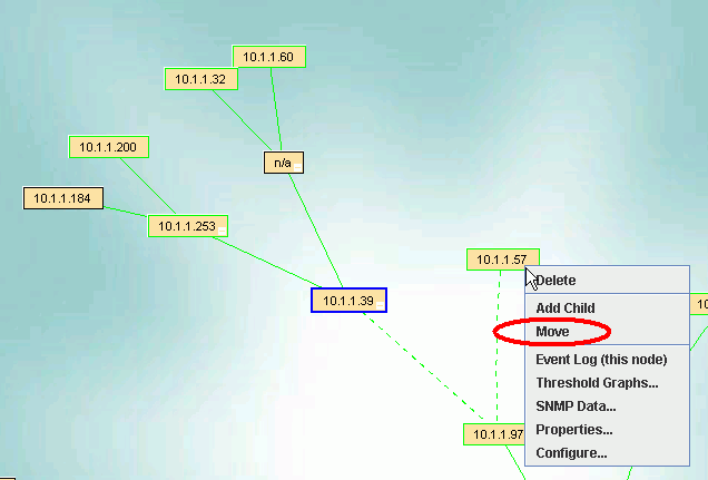
In this case, the .97 is on the IntraVUE side and we want the devices, starting witht the .39, to appear under
Bridge B, the .57, needs to get the devices so we use the Move instructions above.
Select the .39 so it has a blue outline, then right click on the device you want to move to, the .57, and pick Move.
The devices on the other side of the bridge will now be under the .57.
Section 4.8
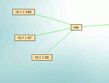
The image below shows the way IntraVUE will display an unmanaged switch having two devices connected to it. If a managed switch
does not have its SNMP community set correctly it will appear the same.
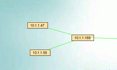
The 10.1.1.169 device is an unmanaged switch with the .47 and .59 devices physically attached.
The parent managed switch of these devices reports them all on the same port, so IntraVUE automatically inserts a node, labeled
'n/a' to represent the hub or unmanaged switch which must be present.
In order to show the network as it physically exists the administrator can select the Configure item from the unmanaged switches
Device Menu.
Check the checkbox 'Unmanaged Switch or Wireless AP' then apply and close.
After a minute, the auto inserted node will go away as there is now only one device on the port of the managed switch and the
other two devices are below it..
Section 4.9
The directory in which IntraVUE was installed contains the following folders:
The Autoip folder contains many files. Those of interest to a user/administrator of IntraVUE are:
The 'tomcat5' folder under autoip contains all the files for the Apache Tomcat eTomcat web server.
This is used be IntraVUE to provide the a user interface to the IntraVUE database.
The only folder of interest to users is the root folder of the web server.
The root folder can be accessed from any computer browsing to the IntraVUE web server.
Users are free to create their own content below this folder, including creating new folders.
The path to the root folder is:
See Configuring Web Links and
Configuring Icons and Thumbnails
for more information on creating your own custom images or adding web content for the IntraVUE web server to provide make available.
When you make a backup from the System Menu or System Config dialog, you are backing up the MySql database that contains all the
data used by IntraVUE. This backup does not contain any content referenced by IntraVUE.
In the event of a catastrophe, installing a new copy of IntraVUE from the installation CD and then restoring a saved backup
will get you to where you were at the time of the backup. Content added by the user will not be in the backup.
Other files that could be backed up via the Windows' backup application or by scheduled tasks might include:
The mysql data files are typically located on hard disk on which IntraVUE was installed, in the \mysql\data folder.
This entire folder and its subfolders MUST BE EXCLUDED from any backup software as well as any antivirus software.
When the mysql database becomes large, these programs will lock critical resources longer than mysql can withstand.
The result will be that mysql stops and consequently the Intravue scanner will not be able to make any updates
until the mysql service is restarted via reboot or by the user.
User created content can only be in the web server root folder described above. All user created content is preserved during upgrades.
Backup the entire root folder to save any content you have added.
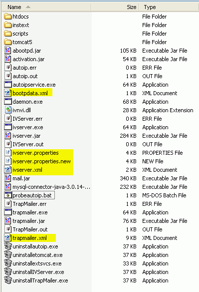
Most configuration data is stored in the mysql database. There are some additional files that also contain configuration data.
User modifications to IntraVUE default files would only be contained in one of the following files, all in the
c:\program files\intravue\autoip\ folder:
bootpdata.xml
contains the configuration data for the optional AutoIP program. Data in this file normally comes from the AutoIP user
interface, the Device Configuration's 'Enable Autoip' checkbox, or by directly editing this XML file. Note that checking the
Enable Autoip checkbox will cause an entry to be added to this file, but unchecking it will not cause it to be removed.
You can only remove an entry using the AutoIP user interface or editing this file in a text editor.
ivserver.properties
contains fine tuning parameters for the scan engine as well as some user interface enhancements that are not yet part of the
browser based user interface.
Each parameter is preceded by an explanation using the comment # sign at the start of each line.
The line starting without a # sign is the actual parameter in use.
Note that when an upgrade is installed, the original ivserver.properties file is updated for any NEW settings,
any existing settings are not changed.
The ivserver.properties.new file contains the default settings for all options, it is not used by Intravue.
This file contains configuration data for the Modbus/TCP interface as well as extra SNMP data that is displayed on a device's
'SNMP Data ...' menu item.
Follow the link for more details.
trapmailer.xml
This file provides extended functionality for getting and sending inforamtion about trap messages. All configuration is done
in this file which is also self documenting in the form of comments.
Note: the full capabilities of trapmailer are complex and require an effort to understand.
Section 5.1 Section 5.2
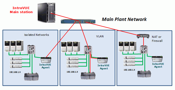
The Scanner Agent was developed to handle several situations:
The Agent performs local scanning of an isolated network and provides the results to the IntraVUE host computer.
The ping and threshold data will be as if the Intravue host computer was located in the isolated network.
Section 5.3 Section 5.4
This file is located in the autoip folder of IntraVUE, normally ...\program files\intravue\autoip
(file system details ) .
Each of the parameters that can be set in this file contains a description of the parameter
and a sample line showing the default value. These are shown as comment lines in the file.
THE FILE IS MEANT TO BE SELF DOCUMENTING.
Comment lines start with a '#' character and have no effect.
This file typically contains configuration items that are not normally changed by
IntraVUE users or administrators. It is usually only changed after consultation
with IntraVUE Technical Support.
Open the file with notepad or wordpad to view the various options or to make changes.
Note: When upgrading to new versions of IntraVUE, this file will be updated for any NEW configuration items. Any settings already applied will not be changed. The new items will be set to their default states.
Section 5.5 Section 5.6
'trunkingdefs.txt' is the default file name.
It is located in the ...\intravue\autoip folder
(file system details ) .
The actual name used is user configurable in the
ivserver.properties
file, in the property 'scanner.trunk.data.file'.
An administrator could then setup several different trunking files for testing and other purposes.
This file is read and interpreted to both combine ports for trunking purposes and also to change
the port numbers assigned to a switch for display purposes.
The format is simple. A switch is designated using square braces, [ ], around its IP address.
This is followed by one or more lines of port assignments until the next set of square braces.
The port assignments are done using a two character separator "->".
On the left is the port as known to the switch.
On the right is how IntraVUE should treat and display that port.
Many ports on the left can be assigned to the same number on the right.
If a number is repeated on the left, the last one will be used.
Example 1 - Normal Case
The 10.1.2.3 switch has ports 2 and 3 trunked to ports 5 and 6 of switch 10.1.2.4. We want IntraVUE
to consider ports 2 and 3 on the 10.1.2.3 to both be treated as port 2 and ports 5 and 6 on the other switch to be treated as port 5.
Example 2 - Showing different port numbers for Stacked Switches
When two 24 port switches are stacked, the port numbers of the second switch are changed internally so they do not conflict with the first switch.
On some switches the first port of the second switch might be numbered 25, or 27 if there are some internal ports, or even a high number like 950.
This example shows the second stacked 8 port switch that has been renumbered for display purposes.
Example 3 - A Switch with misnumbered ports
In this example the label on a switch numbers the ports 1 thru 12, but internally the ports are 12 to 1.
IntraVUE reports the port number used by the switch internally and this leads to confusion.
A Cisco 2955 is an example of such a switch.
Section 5.7
IntraVUE uses port 8765 to view web pages and to communicate internally.
Some users may desire a different port number due to proxy servers or
when going through a firewall. IntraVUE can be configured to 'listen'
or additional port numbers, but will ALWAYS listen on port 8765 which
MUST be available for IntraVUE's use.
Below are the steps to configure the Tomcat web server to use port 80, as an example.
1. Make sure that port 80 is not in use already with some other web server (eg IIS, Apache)
From a command line, do
You should NOT see a line like
If you do, you'll have to find out which web server is using that port and stop it before continuing.
Look down the services list and see if there's anything like httpd, apache, IIS, ...
The other web server must be configured to use another port or must not run to avoid a race for the port on restarts.
2. Using windows explorer, navigate to the directory C:\Program Files\IntraVUE\AutoIP\tomcat5\conf
3. Make a safety copy of the file server.xml by selecting it, then copy (Ctrl-C) and paste (Ctrl-V)
4. Open the file server.xml with notepad (it's a pretty short file - only about 30 lines long)
5. Add an additional line after the assignment to port 8765. YOU MUST NOT REMOVE THE 8765 LINE. So,
6. In the services list , stop and then start the service 'Apache tomcat etomcat'
7. Confirm you can still talk to the IntraVUE server by pointing your browser at URL
8. Confirm it ALSO works on the default port 80 by using URLs
9. You should now be able to see IntraVUE on port 80
Note that you cannot remove the port 8765 from the server.xml file, because some
internal functions expect to find the server on that port. However, all the
applets will use the same port as the original connection, so it should work
fine through firewalls which block port 8765.
Although it is possible in principle to accommodate an existing web server on
port 80 without stopping it, the procedures for doing this are much more
complex, particularly if the goal is to drill through firewalls. I would suggest
IntraVUE be installed on a dedicated machine to avoid these issues.
Section 5.8
There may come a time when you need to increase the node count of your license,
say from 128 nodes to 256 nodes. The limit of a license is contained within
your product key.
Your product key is permanently stored in the green USB dongle and a program
is required to change the product key.
Such a program is installed to the C:\TEMP\RegisterPK folder of the host computer
during IntraVUE installation. This program will be on any computer on which IntraVUE
was installed.
To upgrade your USB dongle with a new product key launch the program RegisterPK.exe in that folder.
There are 3 main steps to changing the product key.
You must get a message that the dongle was successfully written to and updated for the change to take place.
If there is a problem, an error message will indicate the cause.
The most likely problem is a mistake on the registration code when manually entering it.
Note: When you select the 'Read Dongle' button, you are getting the current registration info.
When the Product Key changes the Registration Code also changes to authenticate the new product key.
Section 5.9 Section 5.10 Section -1
Device Menu for Admininstrators
The Device Menu is available by a right click on the device node.
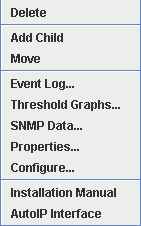 Delete will remove the device and delete it from the database. NOTE: if the device's IP address is in the scan range the device will be rediscovered as soon as it responds to a ping.
Add Child will cause a manually inserted node to be added to the selected device.
Manually inserted nodes will have "N/A" as the initial setting for all device views.
These are captital letters to distinquish them from automatically inserted nodes which are in lower case letters, "n/a".
There will be a black connecting line to one of these nodes until a device which is responding to pings is moved under them.
(You can not change the "N/A" in the IP View but you may change all the other views).
Move will move any selected nodes to the node on which you clicked to bring up this menu.
Configure brings up the Device Configuration dialog which allows you to edit settings, create web links, and assign images.
All other selections on the menu are the same as for the User Mode.
Like the Device Menu for regular users, any web links will be shown at the bottom of the menu.
The last 2 items in the image above are the Web Links for the device selected to create this image.
System Configuration
The System Configuration dialog allows the administrator to perform
many operations which apply to the entire IntraVUE program.
You must be logged in as the Admin to use the System Configuration dialog.
The System Configuration dialog provides full control over IntraVUE
from within a browser interface. There are no additional configuration applications
which must be run on the IntraVUE host computer.
Click on any of the following links for details on each tab.
System Configuration - General Tab
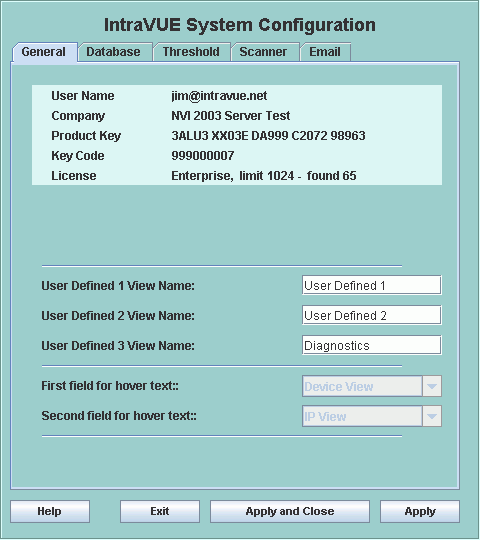 The top section of this tab will provide registration information,
which IntraVUE version is installed, how many nodes have been found and how many nodes IntraVUE is licensed for.
The titles for the 3 user defined views are set in the middle of this tab.
The names here will appear in the browser, system menu, and device configuration,
and device properties dialogs.
The next section allows you to select 1 or 2 view names to be used in the hover text,
see Hover Features. This feature is disabled and will be enabled in version 2.1.
System Configuration - Database Tab
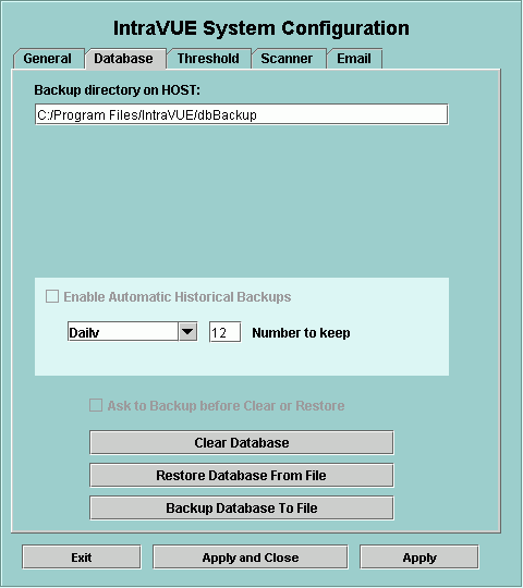 At the top of this tab you may set a folder on the host computer which
will be used to store or retrieve database backups. The setting defaults
to IntraVUE's default database folder each time System Configure is launched.
When the full security model for IntraVUE 2 is implemented it is intended
that only the 'super' administrator can change this field. This could prevent
remote users from browsing file names any place on the host computer.
Automatic Historical Backups provide a series of regular backups without
further user actions. You may schedule the automatic backups to be done
on a daily, weekly, or monthly basis. Whichever interval you select, you
can also set how many of these backups will be kept.
Note: the time of the first backup is loosely based on when automatic backups is enabled
and then will be on 24 hour intervals after that. There is not a control to set the time of backup at this time.
Once the number of backups has been reached, the oldest backup is deleted after a new
backup.
The bottom section allows you to perform the 3 major database operations.
It is not necessary to stop IntraVUE for any of these operations.
Note: A restore does a clear first, so you do not need to manually do a clear before restoring a database.
After restoring a database, you will be asked if you want to be in Off-Line mode. In Off-Line mode
the scanner does not make changes to the database. If you restore a database from an earlier version
of IntraVUE you can only be in Off-Line mode.
If you selected Off-Line mode and would like the scanner to start making changes, restore the database again
and don't select Off-Line mode.
System Configuration - Threshold Tab
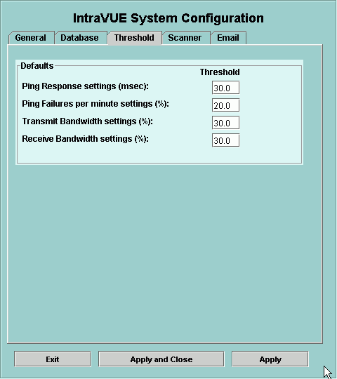 When a device is initially discovered its initial threshold settings
are set based on the values in this dialog.
After a device is discovered, its threshold settings are changed
on an individual basis by right clicking on a connecting line.
System Configuration - Scanner Tab
The Scanner Tab allows you to configure networks and IP Address scan ranges
so you can select the devices you want to monitor with IntraVUE.
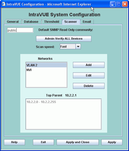
Three buttons allow you to Add, Edit, or Delete networks.
Removing a network or removing devices from a scan range does net delete the devices from the IntraVUE database.
It removes them from active scanning and monitoring. The event history will still be in the database and the
nodes for any discovered devices will still be in the displayed network topology. You need to manually delete
any devices you do not want to be displayed. If you want to remove all traces of a network, use the Clear Database
button in the Database Tab.
Note Regarding SNMP Communities
The SNMP community for a device will not be set until successful SNMP communication to that device.
You may set the default to the value of the switches and let all the switches be learned and then set it to another community
and then those device communities will be set - all without using Device Configure.
At the end we recommend leaving the community set at 'public', the SNMP default, which will apply to most newly discovered devices.
Add an IntraVUE network
Selecting the Add button displays the Network Add Dialog.
If you have VLANs, Virtual Local Area Networks, you should review this document before configuring IntraVUE networks.
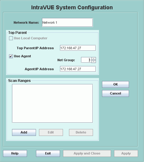

If you are using the IntraVUE Scanner Agent for this Intravue network, check the 'Use Agent' checkbox and additional fields will be available.

Once you have selected the top parent, use the Add button in the Scan Ranges group to add IP Address
ranges until all the devices you want to monitor have been added.
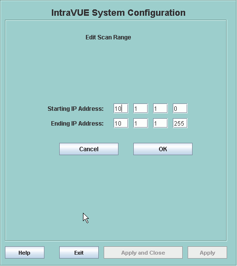
    Example:  Scan only 10.1.1.100

            Starting IP Address 10.1.1.100
            Ending IP Address   10.1.1.100

    Example:  Skip 10.1.1.100

            Starting IP Address 10.1.1.0
            Ending IP Address   10.1.1.99

            Starting IP Address 10.1.1.101
            Ending IP Address   10.1.1.255
Note: If your computer has multiple NIC cards, only one should be in the scan range.
Make sure the you skip over the IP addresses of all other NICs in the host computer.
VLANs - Virtual Local Area Networks
Selecting the Top Parent
What is a Top Parent?
Definitions:
Local is determined by applying the IP address of a computer to its subnet mask.
Pings to local ip addresses will go directly to the device and the MAC will be stored in the host computer's ARP cache.
An online subnet calculator is useful if you have unusual subnet masks.
www.subnetonline.com and
www.subnetmask.info are two examples.
General rules for determining the ‘top parent’:
Example:
IntraVUE host is 10.1.1.35.
Router has IP addresses 10.1.1.1, 10.1.2.1, 10.1.3.1, and 192.168.1.254.
You want to scan all those class C ranges.

Network 1
    top parent  10.1.1.35              (local host to get MACs of local devices)
    range       10.1.1.0 - 10.1.1.255  (includes the router 10.1.1.1 and top parent)

Network 2
    top parent  10.1.1.1
    range       10.1.1.1 - 10.1.1.1 (top parent must be in a scan range)
    range       10.1.2.2 - 10.1.2.255 (exclude the router's 10.1.2.1 address)

Network 3
    top parent  10.1.1.1
    range       10.1.1.1 - 10.1.1.1 (top parent must be in a scan range)
    range       10.1.3.2 - 10.1.3.255 (exclude the router's 10.1.3.1 address)

Network 4
    top parent  10.1.1.1
    range       10.1.1.1 - 10.1.1.1 (top parent must be in a scan range)
    range       192.168.1.1 - 192.168.1.253 (exclude the router's 192.168.1.254 address)
Top Parent Problems
If you do not select the correct top parent, or the top parent is not configured
to successfully use SNMP, you will see something like the image below in your browser.
System Configuration - Email Tab
The Enable Email Alarming checkbox must be enabled for emails to be sent for alarms.
Note that on a new scan checking this checkbox will not result in ANY emails being sent.
That is because, by default, no device will have its 'Send Email to Default User' checked. See Below.
Currently only device disconnect events will generate an email for those devices configured to send email.
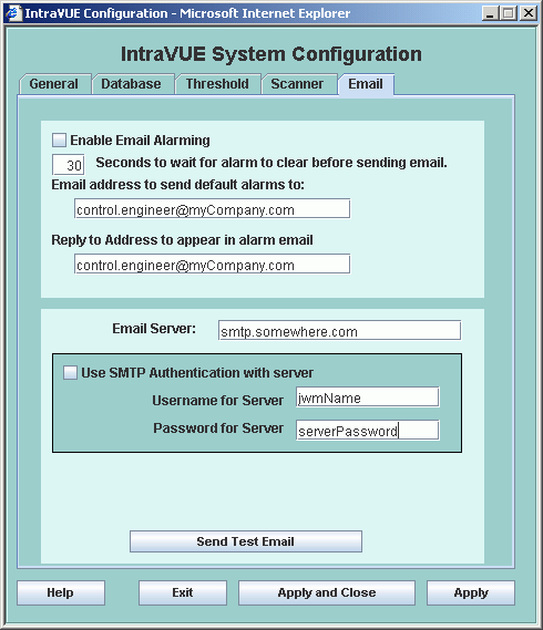 The Seconds to wait ... edit box sets the number of seconds an email alarm will be delayed
before transmission. At the end of the delay time, IntraVUE will check to see if the alarm condition
is still valid. If it is, the email will be sent at that time. 30 seconds is the default setting.
The Email address to send ... field is the email address that will receive the email alarms for all devices.
The Reply to address... field is required when your SMTP server requires a valid email address.
It is also the reply to address that will be on the alarm emails. This address may or may not
have to be valid depending on your SMTP server.
The bottom section of this tab contains the data necessary to connect to the SMTP server
that will be sending the email. The IntraVUE host computer must have access to this
server for email to work.
In the Device Configuration dialog, there is a Enable Alarms To Default User checkbox.
This is NOT checked by default. If checked the default user will get email for this device.
There is also a Enable Alarms To Device User checkbox. If you want an additional email
sent to someone besides the default user, check the box AND edit the Send To field
for the email of the person to get alarms for this particular device.

The Send Test Email button will immediately generate a test email using the settings
IN THE DATABASE. If you make a change, select the APPLY button before selecting Send Test Email.
This feature avoids having to disconnect a device just to test your email settings.
When you use the Test Email button and you do not receive an answer,
there will be some text in an Exception message indicating the specific cause of the failure.
For instance refused by SMTP host, invalid user name or password, etc.
This message is found in the scanner log file located at ...\intravue\log and will be the ivserver_(date)_(time).out file at the time you pressed Test Email.
A sample of what is generated is below. It was generated by doing a Test Email with the default Email Setup dialog.
The stacktrace line "javax.mail.MessagingException: Unknown SMTP host: smtp.somewhere.com;" tells you that the SMTP host,
the email service provider, is incorrect or that you can not connect to it.
0120 100016 event: Device 10.1.1.67 reconnected
0120 100054 event: Device 10.1.1.90 moved from 10.1.1.244:9 to 10.1.1.16:2
0120 100054 event: deleted child node at 10.1.1.244:9
0120 100111 event: 10.1.1.32 Ping Response Threshold Exceeded
0120 100122  received mod request send test email 0 0
0120 100122 send test email
0120 100123 EmailTask runs: Intravue has been instructed by the admin to send a test email. Please see http://10.1.1.59:8765/
 to [unused]
0120 100123 Unexpected Exception thrown - stacktrace follows:
javax.mail.MessagingException: Unknown SMTP host: smtp.somewhere.com;
  nested exception is:
   java.net.UnknownHostException: smtp.somewhere.com
   at com.sun.mail.smtp.SMTPTransport.openServer(SMTPTransport.java:1211)
   at com.sun.mail.smtp.SMTPTransport.protocolConnect(SMTPTransport.java:311)
   at javax.mail.Service.connect(Service.java:233)
   at javax.mail.Service.connect(Service.java:134)
   at javax.mail.Service.connect(Service.java:86)
   at com.sun.mail.smtp.SMTPTransport.connect(SMTPTransport.java:144)
   at javax.mail.Transport.send0(Transport.java:150)
   at javax.mail.Transport.send(Transport.java:80)
   at database.EmailTask.run(EmailTask.java:76)
   at java.util.TimerThread.mainLoop(Unknown Source)
   at java.util.TimerThread.run(Unknown Source)
0120 100146 device 10.1.1.67 disconnected
0120 100146 event: Device 10.1.1.67 disconnected
0120 100207 device 10.1.1.90 reconnected
Customizing the Email Message
The email message that is sent to the user can be customized using options in the
ivserver.properties
file.
Import and Export Functions
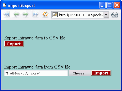
The Import and Export features are accessed from the System Menu.
Export
If you select the Export button, a standard Windows file download dialog will
ask if you want to save the file or open it. If Microsoft Excel or similar spreadsheet
program is installed, you may open the file directly into that. Export files are
saved in plain text, comma separated value (CSV) format.
If you select the Choose... button next to Import, a standard Windows File Save dialog will presented.
Navigate to the file you want to import and select it.
Import
If you select the Import button, the file listed in the filename field will start to be imported.
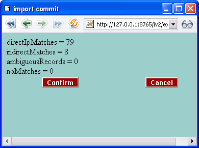 Data is primarily imported based on the IP address field of the saved file.
This makes it possible to import data from files that have been saved from other IntraVUE's
or from previous databases on the host computer.
If a match by IP address is not possible, IntraVUE tries to make a match based on
the parent switch and switch port of a field.
Usually only fields for manually inserted devices connected to other manually inserted devices
would have problems being imported.
You must select the Confirm button to complete the process.
Spreadsheet Notes
When you look at the exported data in a spreadsheet program you will find many columns.
There are 3 basic sections:


Device Configuration
The Device Configuration dialog has 4 tabs that allow you to configure
the unique properties of a device.
Device Configuration - General Tab
This tab sets the general properties of a device.
Admin Verification
Admin Verification is a process of establishing a controlled state of your network,
or the devices which you are monitoring with IntraVUE.
Each Admin Verified node has different characteristics from a non-Verified node.
When all the devices in a network are verified, the nodes in IntraVUE will all be blue.
Some may have yellow or red connecting lines, or even red outlines, but you will
basically be looking at all blue boxes.
To make Admin Verification easy, there is a single button that will automatically
verify every device with an IP address that has not yet been verified. It on the
Scanner Tab of the System Configuration dialog
When a box is tan it will stand out. It will call your attention to it.
Find out what it is and then verify it or take some action to get the device off line.
A red filled node is the 'ghost' of the real position of a device.
In IP View the real device will have a real IP name like 10.1.100.56 and in the
red filled box the IP will be 10-1-100-56.
If you see a red filled box, find the corresponding tan filled box.
If the new position is acceptable, delete the red filled box and admin verify the
new position. In the future this two step process will become one step.
If the position is temporary you may leave the red filled box. When the device
is returned to its former position the red box will be replaced by a blue filled box.
Device Configuration - View Names Tab
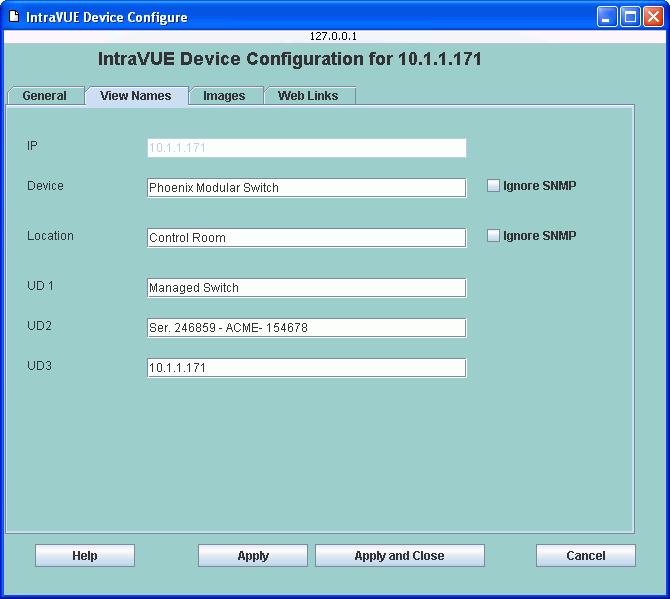
Device and Location names can have Ignore SNMP checked and the scanner will not
use SNMP to get a device's Device name and/or Location field.
Device Configuration - Images Tab
New Images
Browse
Device Configuration - Web Links Tab
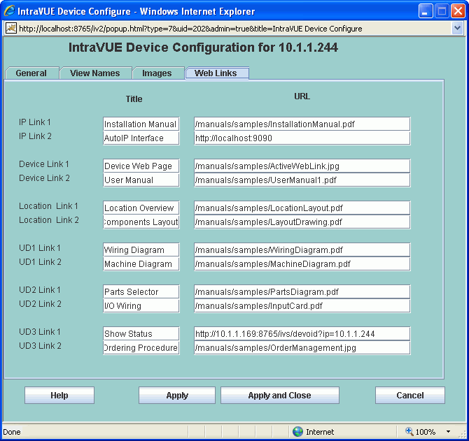
c:\program files\intravue\AutoIP\tomcat5\webapps\ROOT
c:\program files\intravue\AutoIP\tomcat5\webapps\ROOT\manuals\samples\InstallationManual.pdf
/manuals/samples/InstallationManual.pdf
Weblinks to other IntraVUE Hosts
http://10.2.3.44:8765/iv2/ivue.jsp?v=3iT
Manual Moves
Add Child
This adds a new node under the selected device.
This is typically used for devices connected via linking devices.
The properties of the new node can be changed to reflect a device which is in the network but not visible to the scan engine.
Typically, the other devices that are physically connected to the inserted node will be moved graphically to the new node using the MOVE function.
An event log entry is generated for this operation.
Move
Move allows the user to change the parent of a device.
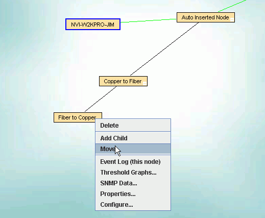
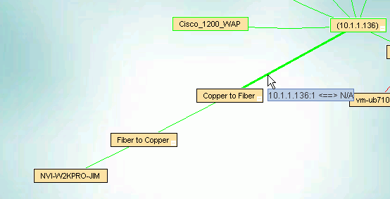
Example of adding Media Converters
Media Converters typically do not have IP addresses. They may take the copper CAT5 cable and convert it to fiber or even wireless.
A second device typically converts the signal back to copper.
Example of Configuring a Bridge
In the image below, the .97 and .57 devices have been discovered as wireless bridges.
IntraVUE will not know which ip address is on the IntraVUE side of the network so you could find
either one as the parent.
Configuring Wireless Access Points and Unmanaged Switches
Unmanaged Switches
An unmanaged switch that has an IP address but which does not support SNMP will be found and displayed under an auto-inserted
node along with the devices that are directly connected to the switch.
This is because they will all be found on the same port of the unmanaged switch’s parent and any lower down managed switches
will see them on the 'uplink' port back toward the IntraVUE host.
Wireless Access Points
Managed Wireless APs should be discovered by IntraVUE and will automatically get the checkbox for 'Unmanaged Switch or Wireless AP'
in the Device Configure dialog checked.
If you have a WAP that is not managed, you can check the checkbox yourself.
The result will be that all wireless devices will appear under the WAP and will have dashed, wireless, lines going to them.
Virtual Machines
If a host computer is setup with Virtual Machines, each VM will appear as a peer of the host, all under an auto-inserted node.
It will look just like an unmanaged switch.
Use the technique above and check the 'Unmanaged Switch or Wireless AP' checkbox and the VM's will be placed under the host.
IntraVUE File Structure
Organization
...\intravue\autoip\tomcat5\webapps\ROOT
Backing up files not in the MySql database backup file.
Special Files in IntraVUE
        bootpdata.xml
        ivserver.properties
        ivserver.xml
        trapmailer.xml
        trunkingdefs.txt
Upgrading from IntraVUE 1 to IntraVUE 2
IntraVUE 1 stored web content under the folder
..\Program Files\Intravue\htdocs.
IntraVUE 2 stores web content under the folder
..\Program Files\Intravue\Autoip\tomcat5\webapps\ROOT
If you have upgraded from a version of IntraVUE before 2.0 this page
explains how to:
Important. IntraVUE 2's file names and path names are case sensitive
when used for images and web links stored on the host computer. If you have
some images or web pages that don't seem to work, check the case first.
(IntraVUE 1's web server was not case sensitive)
Import Device images and web links to the database
This step updates data for each device inside the IntraVUE database.
This is done by using the export/import feature of IntraVUE.
To start you will need an Export from version 1. If you don't have
one you can still make one by restoring the version 1 database and
doing an export of that data from IntraVUE 2.
1. Make a backup of your current IntraVUE 2 database.
2a. If you haven't made an Export, restore your last version 1 database.
(A backup was automatically made and saved as UpgradeBackup.dmp in IntraVUE's dbBackup folder.)
2b. Use Export.from the System Menu, select a location, and save the .CSV file.
3. Use Import from the System Menu, select the location of the saved Export file and import it.
4. Select Confirm. For more information on the meaning of the lines in this dialog, see Import Export
5. The database information for your images and web links has now been updated.
Copy Image Files
This step copies the images and web pages from their IntraVUE 1 location to their IntraVUE 2 location.
For images only (thumbnail and icon images) IntraVUE 1 stored a separate set of images for each
View in folders under htdocs\images. For example there was a folder for all
the images in IP View in the folder ...\htdocs\images\IPview. A total of 6 folders.
For images only, IntraVUE 2 stores all images in a common folder under root named ..\ROOT\Intravue\images.
The reason for the change was based on user feedback indicating the same images were used in all folders.
There are several ways to copy images from each IntraVUE 1 folder location to the common IntraVUE 2 location.
The text below can be pasted into a batch file and perform the entire process in one step. Otherwise,
follow the basic process described below one folder at a time. If you have not installed IntraVUE in the
default location, edit the FROM and TO as appropriate.
- - - - - - - - start - - - - - - - -
 SET FROM=c:\program files\intravue\htdocs\images
 SET TO=c:\program files\intravue\autoip\tomcat5\webapps\ROOT\intravue\images
 copy "%FROM%\ipview\*.*"      "%TO%" /Y
 copy "%FROM%\deviceview\*.*"  "%TO%" /Y
 copy "%FROM%\locatonview\*.*" "%TO%" /Y
 copy "%FROM%\ud1view\*.*"     "%TO%" /Y
 copy "%FROM%\ud2view\*.*"     "%TO%" /Y
 copy "%FROM%\ud3view\*.*"     "%TO%" /Y
- - - - - - - - end - - - - - - - - -
Copy Web Pages
In order for the web links that have been imported into the database from IntraVUE 1 to work with IntraVUE 2,
you must copy the files from the old web server root location to the new web server root location.
If a folder named "manuals" was created under IntraVUE 1's htdocs, you need to copy that folder and all its
files to IntraVUE 2's root folder.
IntraVUE 1's root > ..\Program Files\Intravue\htdocs\manuals
IntraVUE 2's root > ...\Program Files\Intravue\Autoip\tomcat5\webapps\ROOT\manuals
Using the IntraVUE Scanner Agent
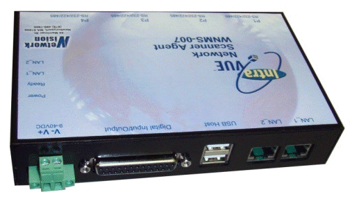
IntraVUE Agents are easily configured with the IntraVUE to provide a complete Industrial Ethernet monitoring solution.
Some OEM systems such as packaging machines or bottling machines contain their own private Ethernet networks.
These systems typically use the same IP addresses for each function in the system.
When you have multiple systems using the same IP addresses it is impossible to monitor networks inside the systems with traditional networking tools.
IntraVUE Agents allow these multiple networks to be monitored by a single IntraVUE package.
Custom Views and Links to the IntraVUE Browser
The properties of the browser when first opened by a user can be
modified in serveral ways.
The initial View, Icons, and Thumbnails
In the ivserver.properties file 'view.settings=' controls the initial settings for icons and thumbnails
and also which view is displayed to the user. There are three characters
after the = sign which dictate these three settings.
The first is the view to be displayed. This is entered as a number
with the following meanings:
		0=Device
		1=IP
		2=Location
		3=User Defined 1
		4=User Defined 2
		5=User Defined 3
The next is the icon value. A capital 'I' means icons on, a small 'i' means icons off.
The next is the thumbnail value. A capital 'T' means thumbnails on, a small 't' means thumbnails off.
In the following example the initial view will be User Defined 1 with icons ON and thumbnails OFF.
view.settings=3It
Using the same syntax you can set or even override these setting by entering
the values in the URL that opens the IntraVUE browser. Append v=3It as a parameter.
Parameters start with a '?' character after the main URL and each parameter is separated by a '&'.
http://192.168.100.55:8765/iv2/ivue.jsp?v=3It
Showing or Hiding Selected IntraVUE networks
If there are many IntraVUE networks in the browser display you may want
to limit which ones can be seen by certain users. Sometimes a router
is added as its own network in order to get MAC addresses but you don't
want to view that in the display.
Each network has a number.starting at 1. To hide a network the setting
'view.hide.networks=' in the ivserver.properties file provides a
comma separated list of networks to hide. The example below, hides the
second network. It may take some experimentation to get the one you intend.
view.hide.networks=2
In a URL this setting would be
http://192.168.100.55:8765/iv2/ivue.jsp?h=2
If you have many IntraVUE networks and you would like to create links to see one or two at a time,
it might become difficult to 'hide' many networks. Instead of using a URL with h=1,2,4,5,6 to only see network 3,
you can use the 'n' parameter to only view networks that are listed. So n=3 is the same as h=1,2,4,5,6 when there are 6 networks.
You can also have more than one after the 'n', as in n=1,3.
The URLs in an HTML tag to create weblinks that individually show networks would look like:
		< a href="http://192.168.100.55:8765/iv2/ivue.jsp?n=1"   > First Network < / a>
		< a href="http://192.168.100.55:8765/iv2/ivue.jsp?n=2"   > Network Two < / a>
		< a href="http://192.168.100.55:8765/iv2/ivue.jsp?n=1,3" > First and Two < / a>
Multiple parameters in URL
Parameters in a URL are separated by a '&' character.
To combine the Hiding of a network AND the view settings in one URL put a '&' between parameters as the example below shows.
http://192.168.100.55:8765/iv2/ivue.jsp?h=2,3,4&v=3TI
The ivserver.properties File
The ivserver.xml File
Modbus/TCP and SNMP Data Configuration
IntraVUE provides connection and SNMP information through an embedded Modbus/TCP server on the default Modbus port, 502.
Additionally, all configured SNMP data is visible in the IntraVUE browser by selecting the SNMP Data... item from the Device Menu.
The information to be provided is configured in the file "ivserver.xml", which is located in the ...\intravue\autoip folder
(file system details ) .
IntraVUE makes information available to HMI and SCADA devices in the same way they would access information in a PLC.
ivServer can also be configured to provide any SNMP variables through the Modbus/TCP interface.
The file starts and ends with a dataserver line.
<dataserver mysql="127.0.0.1">
.....
</dataserver>
There are three other types of lines in the ivServer.xml file, located between the above two lines..
Ping or Connection status
Lines that start with "ping" create Modbus/TCP registers for the current connection status of a device.
Note: Register 0 in the ivserver.xml file is the first 40000 or 4X register in Modbus which has an offset of 1 and which is actually register 4:0001.
    <ping reg="0" ip="192.168.100.2" />
    <ping reg="10" ip="10.1.1.45" />
In the above example, the ping status of the device 192.168.100.2 will be stored in the 0th or first Modbus 4X register.
This is generally referred to as 4:00001 or 400001.
The ping status of 10.1.1.45 will be stored in Modbus register 4:00011.
SNMP Data
Lines that start with "snmp" create values in the MySQL database which are also displayed as additional items in the SNMP Data... selection of the Device Menu.
The scanner makes single, snmpget requests for each <snmp reg="2:ts" ip="192.168.100.254" oid="1.3.6.1.2.1.1.3.0" c="public" disptext="uptime"/>
<snmp reg="10:s10" ip="10.1.1.100" oid="1.3.6.1.2.1.1.1.0" c="public" disptext="description"/>
<snmp ip="192.168.100.254" oid=" 1.3.6.1.2.1.2.2.1.5.1" c="public" disptext="Port 1 Speed"/>
If reg="" or reg is missing from the line, no register will be assigned in the Modbus/TCP server and the information will only display in SNMP Data.
The c= attribute is for the SNMP community of the device.
The disptext= attribute establishes the text you would like to appear for this item in the SNMP Data.dialog.
The OID= value may be a well publicized MIB II item or it can be a very specific OID assigned by the manufacturer of a device
such as an over temperature alarm from a water pump.
The colon after the register number indicates the start of a definition of the data type for the information being retrieved.
Modbus registers are each 2 bytes long.
    reg = "10:i"  means register 10 is a 16 bit integer
    reg = "11:d"  means register 11 is a 32 bit integer and occupies 2 registers
    reg = "13:s10"  means register 13 is a string taking 10 register positions or 20 bytes.
In the second example above the value stored in the Modbus registers will take register 11 and 12 because it is a 32 bit number.
In the 3rd example above the string will take registers 13 through 22 - a total of 20 bytes.
Important Notes
1. When configuring registers be aware of the size of the data to be written to the registers and be careful not to overlap data.
In the case of string data if the data retrieved is longer than the size configured, the data will be truncated to the size configured.
Complete syntax for data types is in the comments of the ivServer.xml file.
2. Any time a query to a SNMP device fails, has an error, or times out the single character "0" will be stored for String data and the number 0 will be stored for Numeric data.
Modbus clients such as HMI or SCADA stations should be programmed to handle or ignore these states.
Networkstatus data
Lines that start with 'networkstatus' provide a bit mask Word in one register. The status will remain in the register for 'durationmsec' milliseconds and then go to 0.
<networkstatus reg="60" durationmsec="15000"/>
'networkstatus' defines a register which will have 4 bits, each of which will generate a 'pulse' whenever an associated event is detected in the IntraVUE database.
The pulse goes from 0 to 1, stays at 1 for the configured duration, then returns to 0.
Each bit is manipulated and timed independently.
If a new event of the same type occurs while the bit is set, a new time period will start.
The events detected and reported in this register are
    bit 0: new device joined network
    bit 1: device disconnected
    bit 2: device reconnected
    bit 3: threshold exceeded
Important Hint
Any time you edit the ivserver.xml file it is wise to open the file in Internet Explorer upon completion.
If there is an XML error, Internet Explorer will tell you the line number of the error.
If there is an error in the file, IntraVUE will ignore the file and continue to operate with the last good settings.
Disabling Modbus TCP
Due to other software, it may sometimes by necessary to disable IntraVUE from acting as a modbus/tcp server.
In these cases edit the ivserver.properties file and change the below value to be 'false'.
modbus.service=true
Handling Trunking in Switches
General
Some switches can be configured to treat two or more ports as if they were a single port.
One reason for doing this is to get more bandwidth between two switches.
Another reason is the result of 'load balancing'.
IntraVUE asks a managed switch for the port number of the MAC devices connected to it.
In the case of trunking, the response could be any of the ports used for trunking.
As a result IntraVUE will see the 'lower' switch as moving frequently between the trunked ports,
and the IntraVUE display will redraw each time there is such a change.
A configuration file has been created that allows the IntraVUE administrator to inform the scanner
of any trunking for switches being scanned.
The 'trunkingdefs.txt' File
    [10.1.2.3]
    2->2
    3->2

    [10.1.2.4]
    5->5
    6->5
    [10.1.2.3]
    10->1
    11->2
    12->3
    13->4
    14->5
    15->6
    16->7
    17->8
    [10.1.2.3]
    1->12
    2->11
    3->10
    4->9
    5->8
    6->7
    7->6
    8->5
    9->4
    10->3
    11->2
    12->1
How to Add an additional web server Port Number
netstat -an
TCP 0.0.0.0:80 0.0.0.0:0 LISTENING
   < Connector port="8765" / >

becomes

   < Connector port="8765" / >
   < Connector port="80" / >
http://127.0.0.1:8765/iv2/list
       http://127.0.0.1:80/iv2/list
       http://127.0.0.1/iv2/list
http://127.0.0.1
Product Key Upgrade
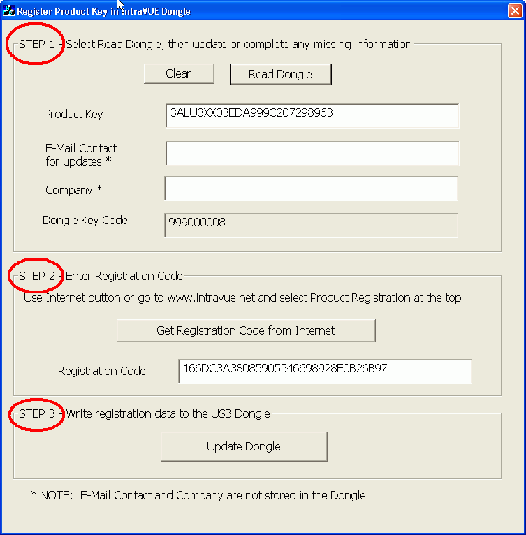
READ ME
A User Forum for IntraVUE is at http://www.NetworkVisionSoftware.com/forum.
The forum contains additional help, facts, and tools.
Users with Service Contracts may post questions and download updates after registering.
Release Notes
Release Notes
are available at the IntraVUE web site.
Upgrade Notes
Errata
Legal Trademarks
IntraVUE is a registered trademark of Network Vision Software Inc., Newburyport, MA 01950
Windows is a registered trademark of Microsoft Corporation.
InXight is a registered trademark of InXight Software, Inc. InXight provides the hyperbolic tree software used in IntraVUE's user interface.
MySQL was a registered trademark of MySQL AB and is now a registered trademark of Sun Microsystems.
The design and user interface of IntraVUE are some of the patent pending inventions held by Network Vision Software Inc., Newburyport, MA 01950
JfreeChart is a free chart library for the Java(tm) platform (C)opyright 2000-2005, by Object Refinery Limited and Contributors.
JFreeChart is used in the Multiple Threshold Lines dialog.
Intravue Help in Other Languages
IntraVUE help is available in the followign languages: